Installation procedure – GAI-Tronics 10461-002 Centra-Page Card Rack User Manual
Page 4
Pub. 42004-220B
Model 10461-002 Centra-Page Card Rack
Page: 4 of 7
\\s_eng\gtcproddocs\standard ioms - current release\42004 instr. manuals\42004-220b.doc
08/05
Installation Procedure
1. Carefully unpack and identify the components. A parts envelope containing the mounting screws and
11 jumper wires is included.
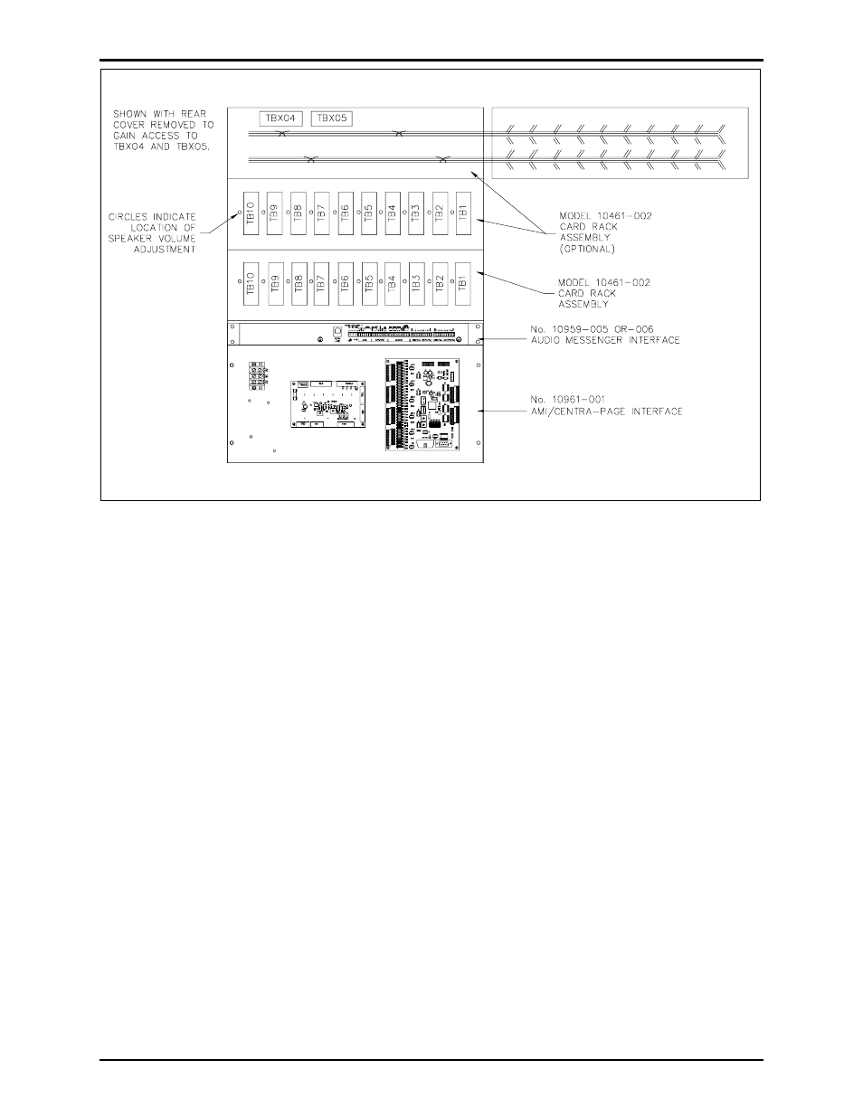
2. Refer to Figure 2. The Model 10461-002 Card Rack(s) is mounted in a Model 10468-002
Centra-Page Central Cabinet, or similar 19-inch cabinet. If mounting more than one card rack or a
Model 10961-001 AMI Centra-Page Interface, all components should be kept together. There should
be no blank panel space between these pieces of equipment or the interconnecting jumpers will not be
long enough.
3. For easy access to TBX04 and TBX05, remove the four screws that hold the back panel on the card
rack. This is the panel with TB1 through TB10 mounted on it. Refer to Figure 2 for details.
4. Carefully swing the panel to the right as if the right side (as viewed from the rear) were hinged. Do
not put excessive strain on the wiring harnesses. TBX04 and TBX05 are now exposed.
5. Connect 22 to 28.8 V dc power to TBX05. If more than one card rack is being used, connect the
TBX05 terminal blocks with the three thick jumpers provided.
6. Connect signal and control conductors to TBX04. Be sure the wiring scheme is consistent from one
rack to the next rack.
7. When reassembling after the jumpers are in place, be certain all harnesses are returned to their
previous locations. Mount the panel to the rear, stationary portion of the Model 10468-002 Central
Cabinet.
Figure 2. General Outline Details