Cabling requirements – GAI-Tronics 10461-002 Centra-Page Card Rack User Manual
Page 5
Pub. 42004-220B
Model 10461-002 Centra-Page Card Rack
Page: 5 of 7
\\s_eng\gtcproddocs\standard ioms - current release\42004 instr. manuals\42004-220b.doc
08/05
8. Wiring from the terminal blocks (TB1 through TB10) on the rear of the card rack to the associated
handset station and speaker can be accomplished in several ways. See Figure 1. In each wiring
option, terminal connections L1, L2, P, and A on the card rack correspond to L1, L2, P, and A on the
terminal strips on each handset station. The remaining two conductors are connected to C and either
70.7 V or 8 ohm for loudspeaker wiring. See the Cabling section below for additional information.
9. Plug the Model 69037-101 Line Cards into the card rack with the card ejectors at the top, and the
components on the right.
10. Adjust the speaker level using a small standard screwdriver inserted into the hole labeled
SPKR.
LEVEL
.
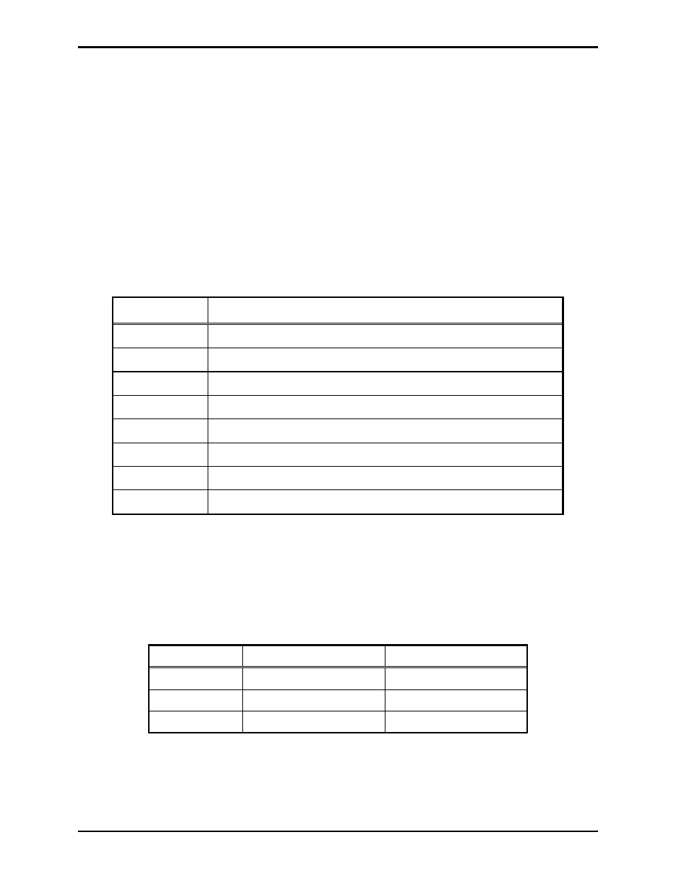
If you are assembling the Centra-Page system in the field, refer to the specific instruction manuals for
individual components. These manuals explain in detail how to install and connect the various
components of a Centra-Page system to the Model 10468-002 Central Cabinet. The manuals for these
components are listed below:
Pub. Number
Component/Title
42004-214
Model 473-002 Centra-Page Outdoor Wall Station
42004-215
Model 472-002 Centra-Page Permanent Indoor 2-Party Station
42004-216
Model 476-002 Centra-Page Flush Mount Station
42004-220
Model 10461-002 Centra-Page Card Rack
42004-221
Model 69037-101 Centra-Page Station Card
42004-227
Model C83018 Centra-Page Station Crew’s Quarters Mute Card
42004-371
Model 10961-001 AMI Centra-Page Interface
42004-345
Model 10959-006 Rack-Mount Audio Messenger Interface
Cabling Requirements
GAI-Tronics recommends the use of three 18 AWG twisted pairs, with each pair of conductors
individually shielded (GAI-Tronics Model 60051 Series cable). However, as longer cable distances are
required, larger wire sizes may be appropriate. The table below lists distance limitations for 1 dB loss for
paging/speaker output.
Wire Size
8-Ohm Output
70.7 V Output
18 AWG
75 feet (25 m)
6250 feet (1900 m)
16 AWG
120 feet (35 m)
9900 feet (3000 m)
14 AWG
200 feet (60 m)
15,800 feet (4800 m)