84503-30 x stanchion panel light installation, Stanchion panel light installation – GAI-Tronics 234WM Wall-Mount Stanchion Assembly User Manual
Page 6
Pub. 42004-308F
Model 234WM Wall-Mount Stanchion Assembly
Page:
6 of 12
f:\standard ioms - current release\42004 instr. manuals\42004-308f.doc
05/11
Model 84503-30
x
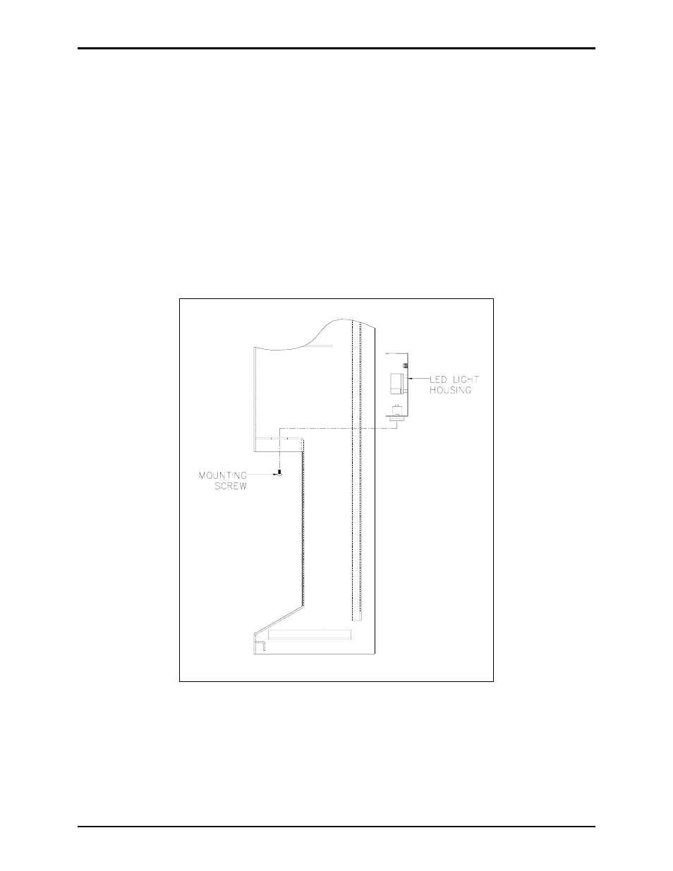
Stanchion Panel Light Installation
1. Align the stanchion panel light assembly inside the stanchion as shown in Figure 5.
2. Model 84503-301: Extend the black (hot), the white (neutral) and the green (ground) wires to the
base of the stanchion (these wires will be connected later, along with the strobe wires, to the incoming
power wires in accordance with the electrical codes).
Model 84503-302: Extend the black (−) and the white (+) wires to the base of the stanchion (these
wires will be connected later, along with the strobe wires, to the incoming power wires in accordance
with the electrical codes).
3. Secure the panel light assembly with the two mounting screws provided. Apply a small amount of
clear RTV silicone sealant or equivalent to each screw thread to reduce the possibility of rust forming
in the screw threads.
Figure 5. Stanchion Panel Light Assembly