Emergency telephone installation – GAI-Tronics 234WM Wall-Mount Stanchion Assembly User Manual
Page 8
Pub. 42004-308F
Model 234WM Wall-Mount Stanchion Assembly
Page:
8 of 12
f:\standard ioms - current release\42004 instr. manuals\42004-308f.doc
05/11
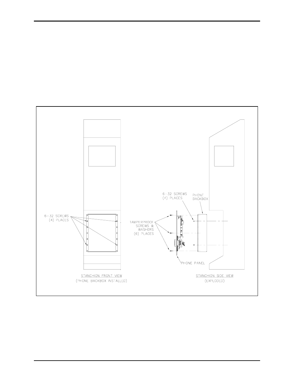
Emergency Telephone Installation
1. Separate the back box from the front panel of the telephone. The parts envelope inside the back box
contains eight #6-32 self-tapping flat head screws, six tamperproof screws, six washers, and a hole
plug.
2. Place the back box into the telephone opening from the front of the stanchion. Mount the box using
four of the #6-32 self-tapping flat head screws. Refer to Figure 7 below. The telephone back box has
two openings, one in the top and one in the bottom. Plug the top opening with a hole plug. The
bottom of the back box is the recommended entry location for the telephone line and strobe control
wires.
Figure 7. Telephone and Back Box Installation
3. Install a telephone line surge suppressor (sold separately) on the protection bracket on the bottom of
the stanchion wall-mounting assembly. See Figure 3.
4. Install a ground wire between the telephone line surge suppressor (sold separately) and the grounding
lug on the bottom of the stanchion. See Figure 8.
5. Connect the telephone line to the surge protection as shown in Figure 8.