Connectors, Power connector – GAI-Tronics 4512-001 6-Channel Radio User and Installation Manual User Manual
Page 5
Advertising
Pub. 42004-387G
Model 4512-001, 4512-001FR, 4514-001, and 4514-001FR 6-Channel Radios
Page 3 of 19
f:\standard ioms - current release\42004 instr. manuals\42004-387g.doc
02/15
Connectors
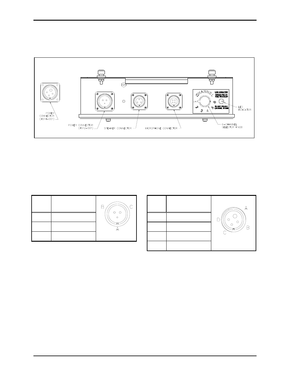
Refer to Figure 3 below for the location of the connectors and channel selector switch.
Power Connector
Refer to Figure 3 for the locations of the connectors. The pinout for the power connector is as follows:
Table 1. Model 4512-001 Connector Pinout
Table 2. Model 4514-001 Connector Pinout
Pin
No.
Function
Pin
No.
Function
A Spare
A Line
hot
B
270 V dc pos
B
Line neutral
C
270 V dc neg
C
Spare
D Spare
Figure 3. Top View of the 6-Channel Radio
Advertising
This manual is related to the following products: