Radio transceiver module, Interface pcba, Pot r7 – GAI-Tronics 4512-001 6-Channel Radio User and Installation Manual User Manual
Page 7
Pub. 42004-387G
Model 4512-001, 4512-001FR, 4514-001, and 4514-001FR 6-Channel Radios
Page 5 of 19
f:\standard ioms - current release\42004 instr. manuals\42004-387g.doc
02/15
Radio Transceiver Module
The Radio Transceiver Module’s range is 450–470 MHz, and the six channel frequencies can be
programmed in steps of 12.5 kHz at the factory to the customer’s specifications. The Radio Transceiver
can also be programmed for CTCSS or DPL.
N
OTES
:
1. When the Radio Transceiver Module is programmed for CTCSS or DPL it can only communicate with
other radios that have the same CTCSS or DPL programming.
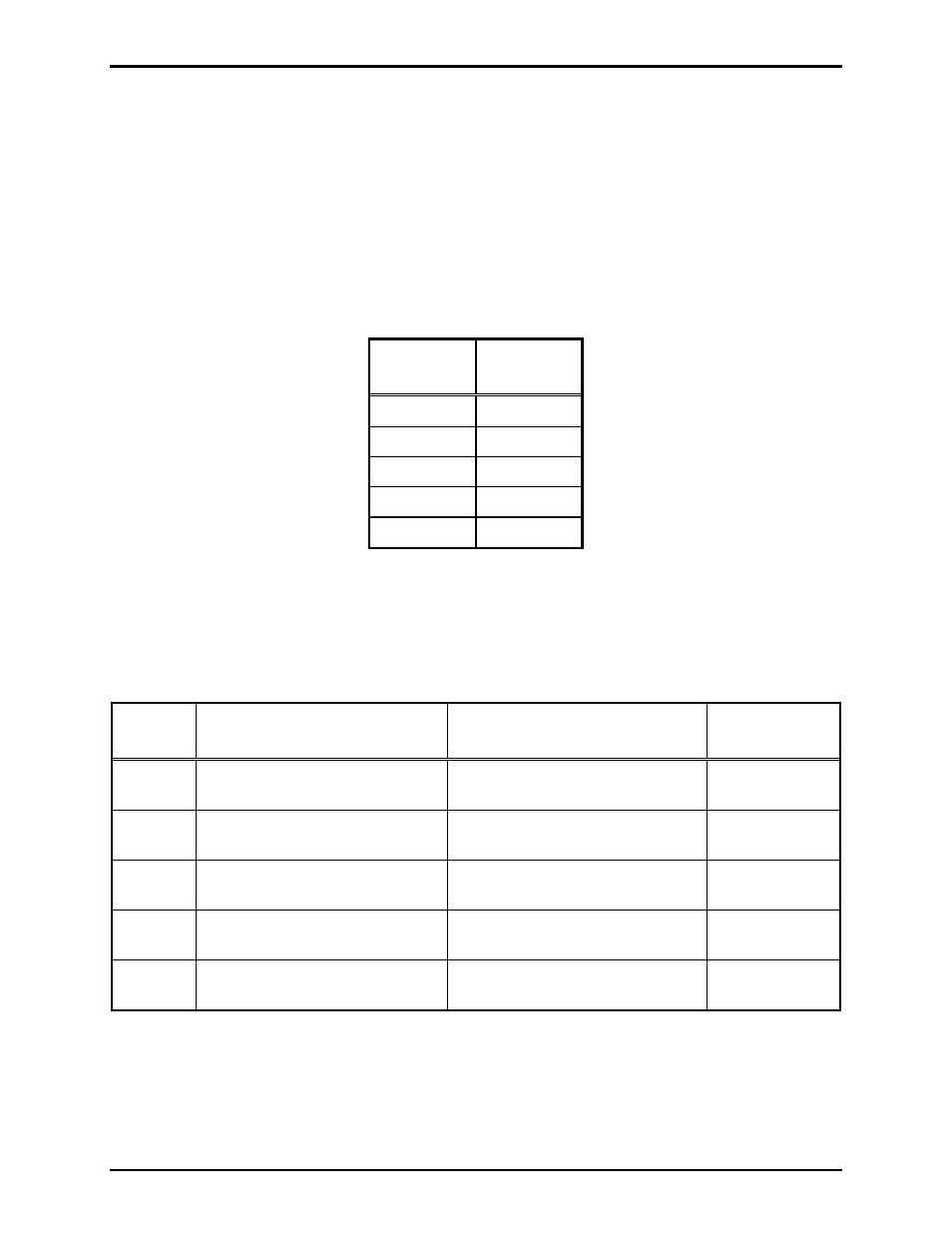
2. Certain transmit and receive frequencies within the radio’s range are unavailable. Refer to Table 5
below for these frequencies. Do not attempt to program the radio for these frequencies.
Table 5. UHF (450–470 MHz)
Receive
(MHz)
Transmit
(MHz)
460.80000 460.78750
461.23750 460.79375
461.24375 460.80625
461.25625 460.81250
461.26250
Interface PCBA
The Interface PCBA contains four jumper settings, which can be configured in accordance with Table 6
below.
Table 6. Jumper Table
Jumper
Name
Function
Position
Default
(as shipped)
P1
Receive Audio Level Select
1-2 = High level
2-3 = Low level attenuated 14 dB
1–2
P4
Audio Amp Enable
1-2 = Enable
2-3 = Disable
1–2
P5
Dynamic Mic/Carbon Mic Enable 1-2 = Enable
2-3 = Disable
1–2
P6
Optional Carrier Detect Output
1-2 = Disable
2-3 = Enable*
1–2
P8
RF Output Power Selection
1-2 = Low Power (2-watt)
2-3 = High Power (5-watt)
1–2
Pot R7
R7 is used to adjust the speaker level. Refer to Figure 4 on page 7 for the location of the pot. Refer to the
“Installation” section for instructions for speaker output adjustment.