Speaker connector, Microphone connector, Antenna connector – GAI-Tronics 4512-001 6-Channel Radio User and Installation Manual User Manual
Page 6: Channel selector switch
Pub. 42004-387G
Model 4512-001, 4512-001FR, 4514-001, and 4514-001FR 6-Channel Radios
Page 4 of 19
f:\standard ioms - current release\42004 instr. manuals\42004-387g.doc
02/15
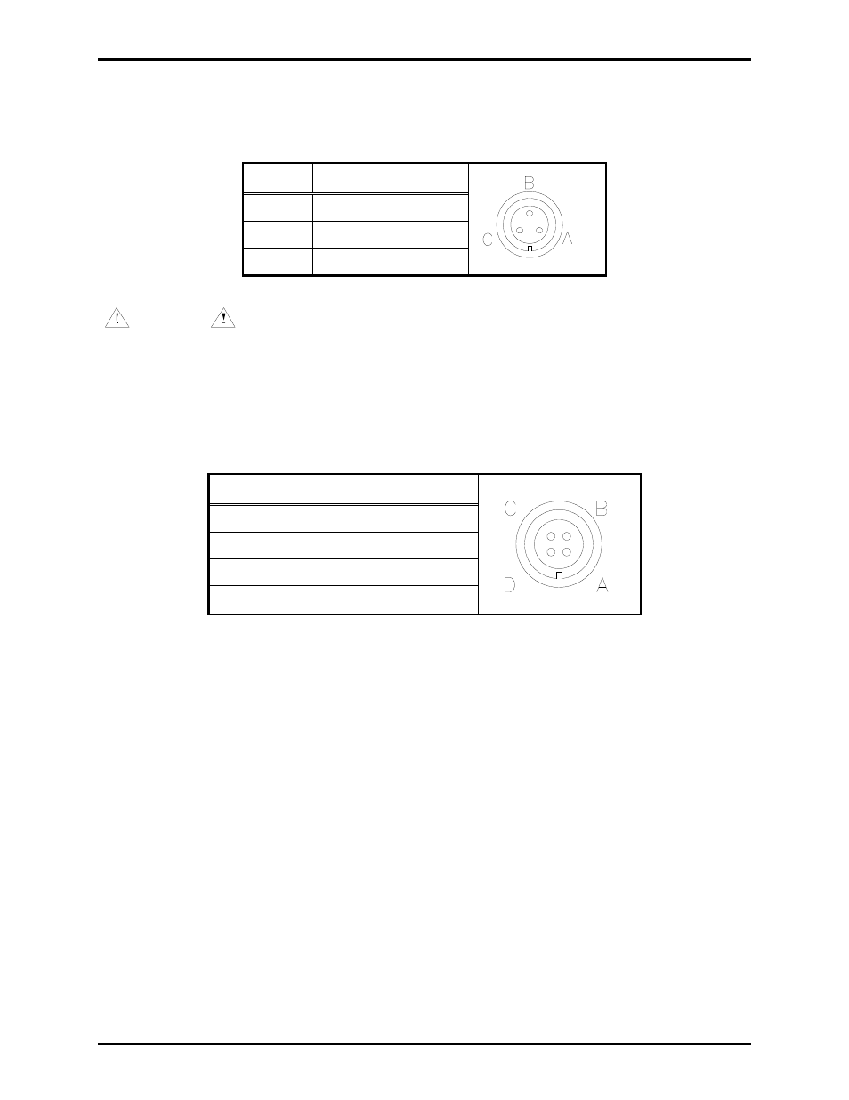
Speaker Connector
The speaker connector pinout is as follows:
Table 3. Speaker Connector Pinout
Pin No. Function
A Common
B
Carrier detect output
C 8-ohm
speaker
WARNING
Do not ground any speaker line as damage may occur to the speaker and/or
radio. Jumper P6 must be in position 2-3 to activate the carrier detect output. Refer to Table 6 on
page 5 and Figure 7 on page 12.
Microphone Connector
The microphone pinout is as follows:
Table 4. Microphone Connector Pinout
Pin No. Function
A Mic
high
B PTT
(Transmit
key)
C Mic
Lo
D
15 V dc power
Antenna Connector
The antenna connector is a coax cable connector.
Channel Selector Switch
The channel selector switch on the top of the unit allows easy selection among the six labeled channels.
In addition, a lighted LED provides indication of the state of the radio.