70x & 398-70x, Stanchion or flush-mount applications – GAI-Tronics 393-700 RED ALERT 300 Series Hands-free VoIP Telephone Manual User Manual
Page 12
P
UB
.
42004-441G
H
ANDS
-
FREE
V
O
IP
T
ELEPHONES
P
AGE
10 of 24
e:\standard ioms - current release\42004 instr. manuals\42004-441g.doc
02/15
Models 397-70
x
and 398-70
x
Stanchion or Flush-Mount Applications
The mounting and wiring instructions are as follows:
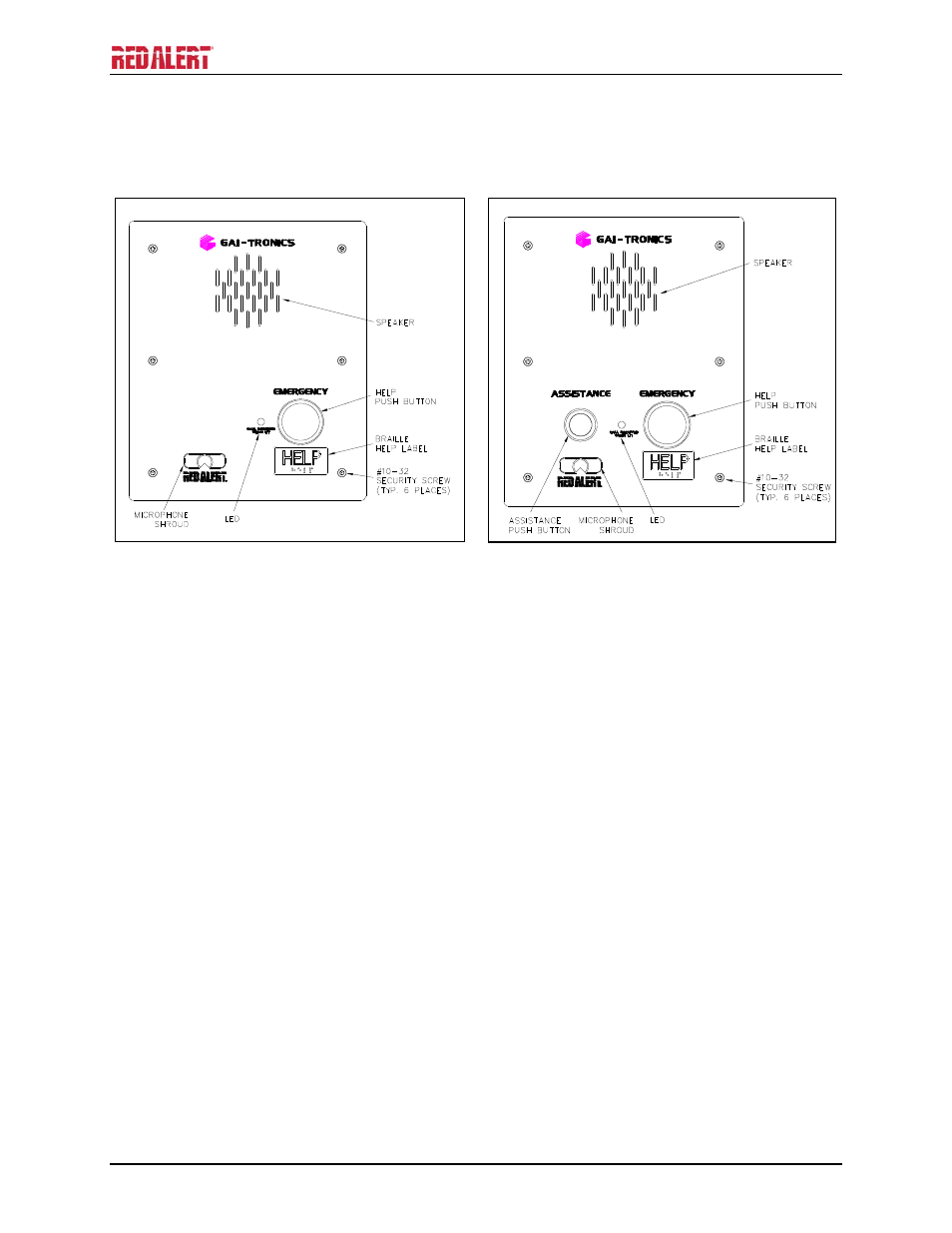
Figure 9. Model 397-700
Figure 10. Model 397-701
1. Use the supplied back box to mount the Model 397-700, 397-701, 398-701 and 398-702 VoIP
Telephones in flush-mount applications or in a GAI-Tronics Model 234 Series Stanchion. Mount the
back box to the structure using the appropriate hardware. Refer to Figure 15 cutout dimensions.
N
OTES
:
When installing a RED ALERT
®
Flush-mount VoIP Telephone in a GAI-Tronics 236-00x Series
or 238-001 Surface-Mount Enclosure, the front panel assembly mounts directly to the enclosure
(back box is not required.)
When mounting outdoors, the installation of a (customer-supplied) surge suppressor on the
Ethernet line is recommended, and the power line, if used.
2. Remove a tapered plug from one of the cable entry holes in the back box, and install the cable and
cable fitting. See the “Field Wire Installation” section on page 14.
3. Use silicone sealant or equivalent around and inside all conduit entries.
4. Connect any desired peripheral devices. Refer to page 18 for connection information.
5. Perform the initial programming of the telephone. Refer to the “Programming” section beginning on
page 19.
6. Verify operation by calling to and from another telephone. Verify operation of peripheral equipment.
7. Attach the telephone’s front panel to the mounting flanges of the back box using the six supplied
#10-32 security screws and washers, 10–12 in-lbs. of torque recommended.
- 393AL-700 RED ALERT 300 Series Hands-free VoIP Telephone Manual 397-700 RED ALERT 300 Series Hands-free VoIP Telephone Manual 398-701 RED ALERT 300 Series Hands-free VoIP Telephone Manual 394AL-702 RED ALERT 300 Series Hands-free VoIP Telephone Manual 397-701 RED ALERT 300 Series Hands-free VoIP Telephone Manual 398-702 RED ALERT 300 Series Hands-free VoIP Telephone Manual