Setup, Field wire installation, Power – GAI-Tronics 393-700 RED ALERT 300 Series Hands-free VoIP Telephone Manual User Manual
Page 16: Power-over-ethernet (poe), Local power, Ground
P
UB
.
42004-441G
H
ANDS
-
FREE
V
O
IP
T
ELEPHONES
P
AGE
14 of 24
e:\standard ioms - current release\42004 instr. manuals\42004-441g.doc
02/15
Setup
Field Wire Installation
After all the field wires are pulled through the rear enclosure, install all connections as indicated below.
Refer to Figure 16 for wiring details. Refer to Table 5 on page 17 for the recommended conductor sizes.
N
OTE
: Consult the National Electrical Code (NFPA 70), Canadian Standards Association (CSA 22.1),
and local codes for the specific requirements regarding your installation. Install all equipment without
modification and according to the local and national codes. Class 2 circuit wiring must be performed in
accordance with NEC 725.55.
Power
Power-Over-Ethernet (PoE)
Connect power to the system as indicated in your PoE equipment manual.
Local Power
When PoE is not available, a separate, isolated 24–48 V dc power supply is required. See the
“Replacement and Optional Parts” chart on page 24 for recommended optional plug-in power supply
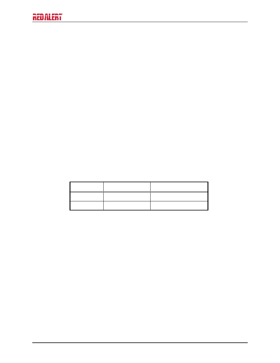
(required only if PoE is not available.) A removable terminal block P5 has been provided for connection
of local power to the telephone. Connect the positive conductor to the (+) terminal and the negative
conductor to the (−) terminal of P5. See Figure 16 for wiring and location of P5.
Table 2. Power – P5
Pin Label
Description
1 (+)
Positive
2 (−) Negative
Ground
The enclosure must be connected to earth ground. Install a #6 ring lug on the ground conductor and
secure it with the ground terminal located on the rear of the front panel. See Figure 8 and Figure 14.
- 393AL-700 RED ALERT 300 Series Hands-free VoIP Telephone Manual 397-700 RED ALERT 300 Series Hands-free VoIP Telephone Manual 398-701 RED ALERT 300 Series Hands-free VoIP Telephone Manual 394AL-702 RED ALERT 300 Series Hands-free VoIP Telephone Manual 397-701 RED ALERT 300 Series Hands-free VoIP Telephone Manual 398-702 RED ALERT 300 Series Hands-free VoIP Telephone Manual