Hardware configuration, External, Internal – GAI-Tronics 400-003 IEC / ATEX Zone 1 RigCom Station User Manual
Page 4
Pub. 42004-460A
Model 400-003 IEC/ATEX Zone 1 RigCom Station
Page: 4 of 16
f:\standard ioms - current release\42004 instr. manuals\42004-460a.doc
09/12
Hardware Configuration
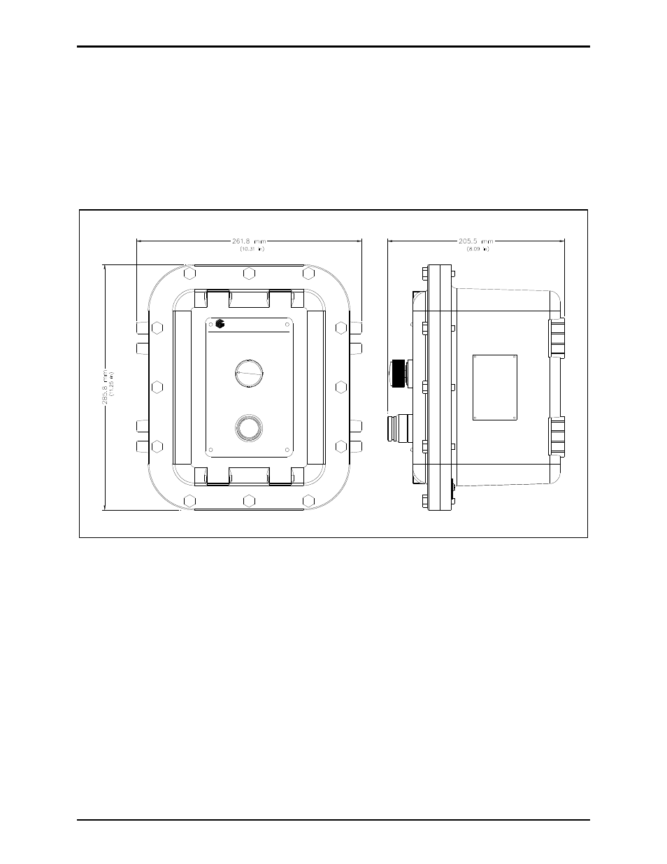
External
The enclosure contains a push-to-call push button, an on-off/volume control switch and applicable
approval labeling. There are twelve 5/16-18
1.25-inch cover mounting bolts located around the
perimeter of the enclosure.
The enclosure has an external grounding screw located on the underside of the flange. See Figure 2.
OFF-ON
VOLUME
PUSH TO CALL
GAI-TRONICS CORPORATION
400 E. Wyomissing Ave., Mohnton, PA 19540 USA
SERVICE CENTERS: In USA: 1-800-492-1212 Outside USA: 1-610-777-1374
Figure 3. Model 400-003 RigCom Station Outline
Internal
The enclosure contains a single PCBA to which all customer cable terminations are made. Internal
connections to the front cover assembly are by a plug-in single wiring harness with a plug. Internal
grounding terminals are provided for ground connection.