Voip pcba connections in the model 13382 – GAI-Tronics 13382 WiFi and VoIP Addressable Amplified Speakers Manual User Manual
Page 21
Pub. 42004-462A
Model 13382 WiFi and 13383 VoIP Addressable Amplified Speakers
Page 19 of 24
f:\standard ioms - current release\42004 instr. manuals\42004-462a.doc
12/13
VoIP PCBA Connections in the Model 13382
For the Model 13382 the WiFi PCBA must be configured prior to configuring the assembly. (See page
11.)
Power the unit by local power by connecting dc power to the terminal blocks on the back box.
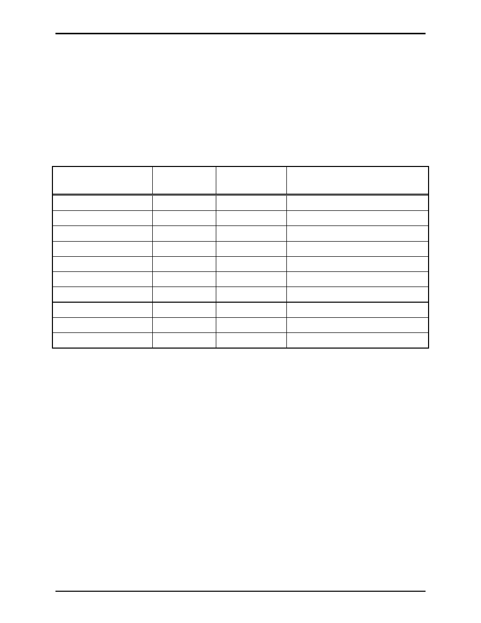
The wiring terminal strip, TB101, is located on the rear section of the speaker assembly. The screw
terminal designations for all models are as shown below. Refer also to Figure 7.
Table 4. TB101 Wiring Description
Terminal Strip
Label Connection
Gauge Wire
Function
DC
POWER
+
TB2-1
No. 20 AWG
Ground reference (local supply)
DC
POWER
−
TB2-2
No. 20 AWG
Ground reference (local supply)
SPARE
SPARE
OPTO
OUTPUT
NO
(2)
TB1-7
No. 22 AWG
Solid state relay positive output
OPTO
OUTPUT
C
(2)
TB1-14
No. 22 AWG
Solid state relay negative output
AUDIO
OUT
600
L1
TB1-8
No. 22 AWG
Positive audio output
AUDIO
OUT
600
L2
TB1-1
No. 22 AWG
Negative audio output
RELAY
C
(1)
TB3-4
No. 18 AWG
Common relay connection
RELAY
NO
(1)
TB3-3
No. 18 AWG
Normally open relay