Block diagram, Interfaces – GAI-Tronics 780-301 Page/Party Handset Station (Cenelec Zone 1) User Manual
Page 4
Pub. 42004-638L2
Model 780/7805-301 Page/Party
®
Handset Stations for Cenelec Zone 1 Applications
Page: 4 of 15
\\s_eng\gtcproddocs\standard ioms - current release\42004 instr. manuals\42004-638l2.doc
6/98
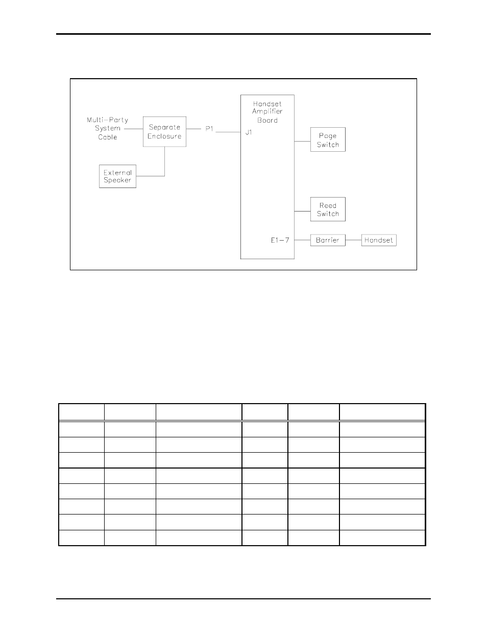
Block Diagram
P1 is the 16-pin male connector located on the back of the Base-16 printed circuit board assembly
(PCBA). It plugs into the socket located inside the enclosure. The socket provides connection to the
multi-party or single party cable containing the Page/Party
®
lines and ac power. The handset amplifier
PCBA connects to the handset and reed switch using lug connections E1 to E7. See Figure 4.
Interfaces
The assembly interfaces to the multi-party cable and the external loudspeaker via P1, the 16-pin
connector, and connector J1. The pin functions for connector P1 are described below:
Pin No.
Function
Description
Pin No.
Function
Description
1
PL_L1
Party line (L1) 9
PL_L2
Party line (L2)
2
PG_L1
Page line (L1) 10
PG_L2
Page line (L2)
3
MT_L1
Mute (L1) 11
MT_L2
Mute (L2)
4
N/C
No connection
12
N/C
No connection
5
SPKR_8
Speaker (8-ohm)
13
EGND
Earth ground
6
SPKR_16
Speaker (16-ohm)
14
SPKR_C
Speaker (common)
7
N/C
No connection
15
N/C
No connection
8
AC_N
AC neutral
16
AC_H
AC hot
Figure 4. Model 701-202-EX Handset Station Block Diagram