GAI-Tronics 69609-001 Dual Page/Party Interface PCBA User Manual
Page 5
Pub. 42004-729L2A
69609-001 Dual Page/Party
®
Interface PCBA
Page: 5 of 16
f:\standard ioms - current release\42004 instr. manuals\42004-729l2a.doc
09/09
Position 4: Extended Board ID A
This switch is used in conjunction with rotary switch SW2 to determine the Board ID value for Zone A.
Refer to the “Board ID Rotary Switches (SW2 and SW3) Settings” section on page 3 for more
information.
Position 5: FSK Test Mode Enable A
This switch may be used to force activation of the FSK carrier signal at Zone A. A continuous alternating
1-0 data pattern at 2400 bps is produced. This switch must be left in the OPEN position for normal
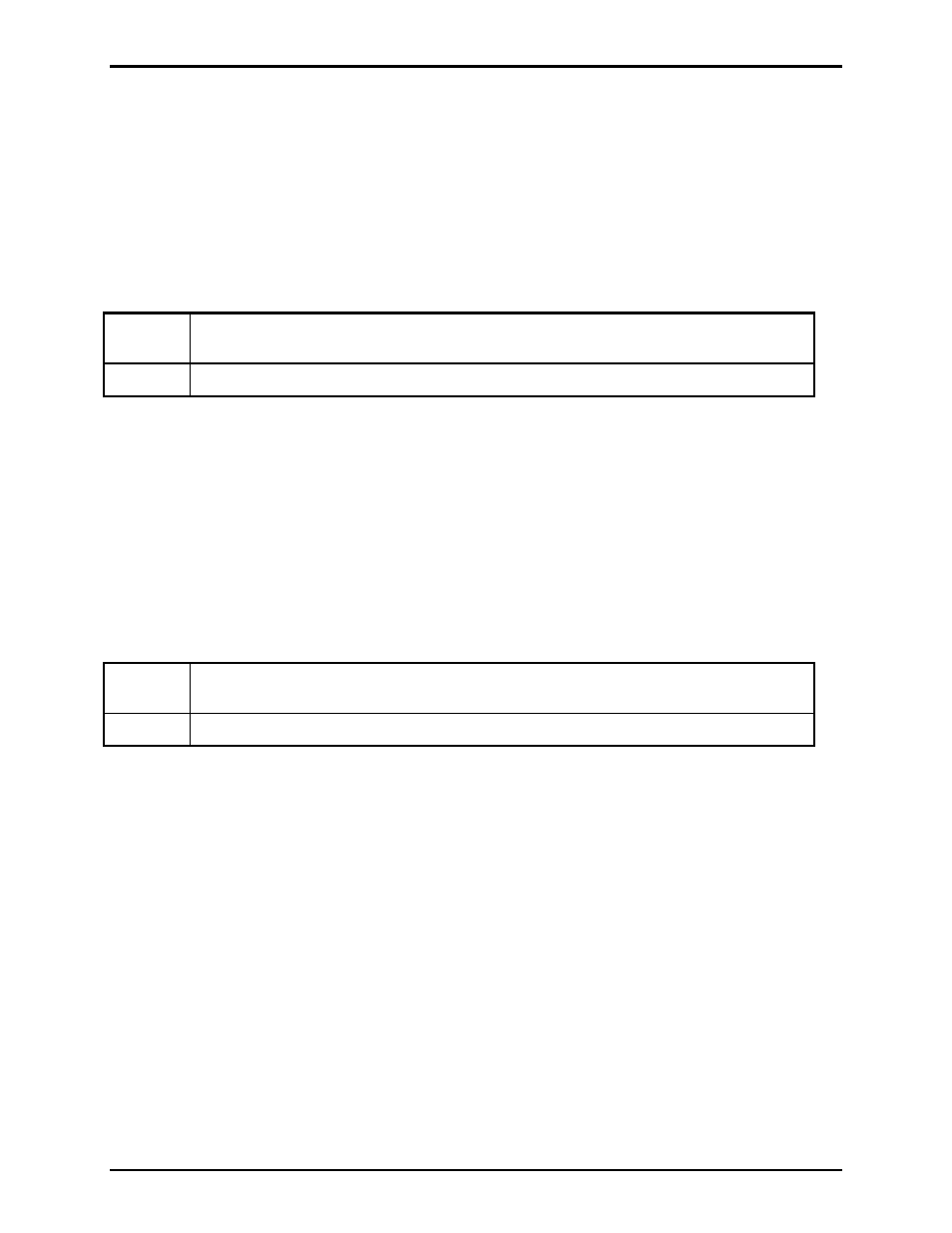
system operation. The following table defines the operation of this switch:
OPEN
FSK Test Mode for Zone A is Disabled (Must be left in this position for normal
operation.)
CLOSED
FSK Test Mode for Zone A is Enabled.
Position 6: Extended Board ID B
This switch is used in conjunction with rotary switch SW3 to determine the Board ID value for Zone B.
Refer to the “Board ID Rotary Switches (SW2 and SW3) Settings” section on page 3 for more
information.
Position 7: FSK Test Mode Enable B
This switch may be used to force activation of the FSK carrier signal at Zone B. A continuous alternating
1-0 data pattern at 2400 bps is produced. This switch must be left in the OPEN position for normal
system operation. The following table defines the operation of this switch:
OPEN
FSK Test Mode for Zone B is Disabled (Must be left in this position for normal
operation.)
CLOSED
FSK Test Mode for Zone B is Enabled.
Position 8: Reserved
This switch is currently unused by the Dual PPI and should be left in the OPEN position.