GAI-Tronics 69609-001 Dual Page/Party Interface PCBA User Manual
Page 8
Pub. 42004-729L2A
69609-001 Dual Page/Party
®
Interface PCBA
Page: 8 of 16
f:\standard ioms - current release\42004 instr. manuals\42004-729l2a.doc
09/09
•
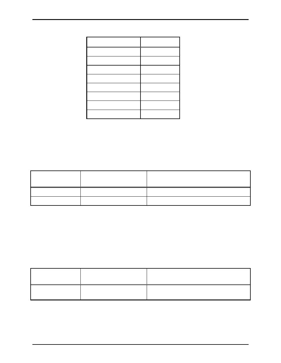
The following settings for SW4 are recommended for most installations:
Switch (SW4)
Setting
Position 1
OPEN
Position 2
CLOSED
Position 3
CLOSED
Position 4
OPEN
Position 5
OPEN
Position 6
OPEN
Position 7
OPEN
Position 8
OPEN
Note that Position 2 of SW4 must be CLOSED in order to disable Zone B. Refer to the “Board
Configuration DIP Switch (SW4) Settings” section on page 4 for more information on these settings.
•
For most installations, the Page Balance Select (P6 and P7) jumpers should be set to the “EN”
position (internal page balance enabled.)
•
When setting the Monitor Bus Transmit/Receive jumpers for the Dual PPI, use the following
conversion table as a guide:
Jumper(s) on
Dual PPI
Equivalent Jumper(s)
on PPI
Notes
P8/P9
J6/J8/J11/J12
Zone A Page Audio → Monitor Bus
P12 J9/J10
Monitor
Bus
→ Zone A Page Line
N
OTE
: Jumpers P10, P11, and P13 should all be placed in the “DIS” position in this case.
Tips on Using a Dual PPI to Replace Two 69255-001 PPI Boards
•
The first step that should be performed when using a Dual PPI to replace two 69255-001 PPI boards
is to decide which 69255-001 PPI board will be mapped to Zone A of the Dual PPI and which will be
mapped to Zone B. Hereafter, based on this mapping, the two 69255-001 PPI boards will be referred
to as the “Zone A PPI” and “Zone B PPI.”
•
When setting the board address for the Dual PPI, use the following conversion table as a guide:
Switch on
Dual PPI
Equivalent Switch
on PPI
Notes
SW1
S1 on either Zone A PPI or
Zone B PPI
Assigns middle nibble of board address