GAI-Tronics 12250-004 Volume Level Control Receiver Assembly (24 V dc) User Manual
Page 3
Pub. 42003-204A
M
ODEL
12250-004
V
OLUME
L
EVEL
C
ONTROL
R
ECEIVER
A
SS
’
Y
(24
V
DC)
R
EPLACEMENT
K
IT
Page:
3 of 6
\\s_eng\gtcproddocs\standard ioms - current release\42003 kit manuals\42003-204a.doc
06/04
Disassembly
1. Loosen the four front panel screws, and remove the amplifier from the enclosure.
2. Loosen the four screws on the side, and slide the chassis to remove the front panel. If the unit does not
contain a handset, immediately set the front panel aside.
3. If the unit contains a handset, disconnect the wires at the printed circuit board assembly (PCBA), and
set the front panel aside. Note the wire color and location prior to removal to allow for easier re-
assembly.
N
OTE
:
Skip Step 4 if the amplifier does not have a chassis-mounted transformer.
4. Place the chassis on the bench with the connector toward you. Disconnect the transformer by removing
the two mounting screws. Disconnect the 6-pin Molex connector from the PCBA, and set it aside.
CAUTION
Removal of the PCBA before drilling is advisable.
5. Loosen the two screws holding the amphenol connector to the chassis.
6. Using pliers, press the plastic standoffs through the back of the chassis to remove the PCBA. Set the
PCBA aside. Be careful not to break the standoffs when pushing them through.
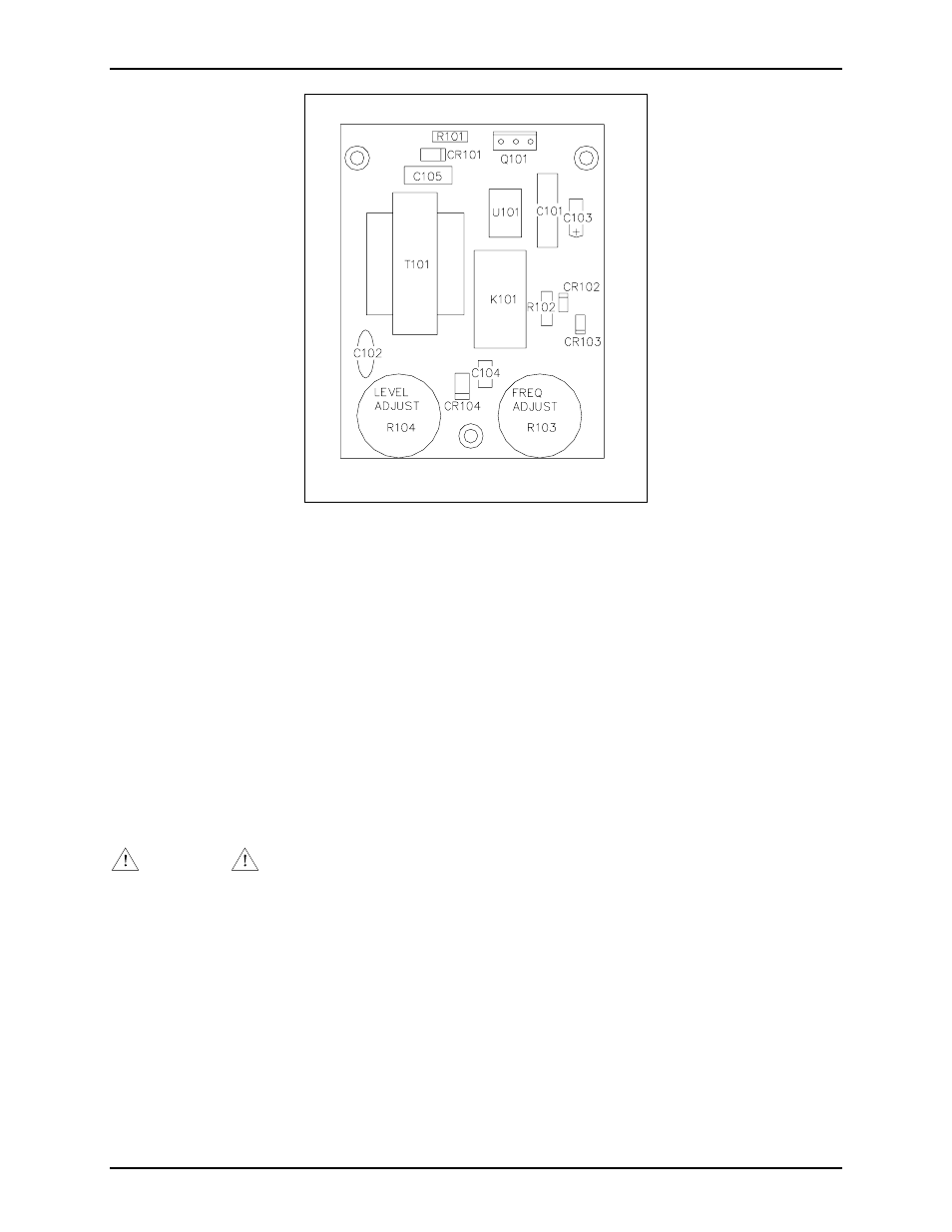
Figure 2. VLC PCBA Component Location