GAI-Tronics 12250-004 Volume Level Control Receiver Assembly (24 V dc) User Manual
Page 5
Pub. 42003-204A
M
ODEL
12250-004
V
OLUME
L
EVEL
C
ONTROL
R
ECEIVER
A
SS
’
Y
(24
V
DC)
R
EPLACEMENT
K
IT
Page:
5 of 6
\\s_eng\gtcproddocs\standard ioms - current release\42003 kit manuals\42003-204a.doc
06/04
Re-assembly
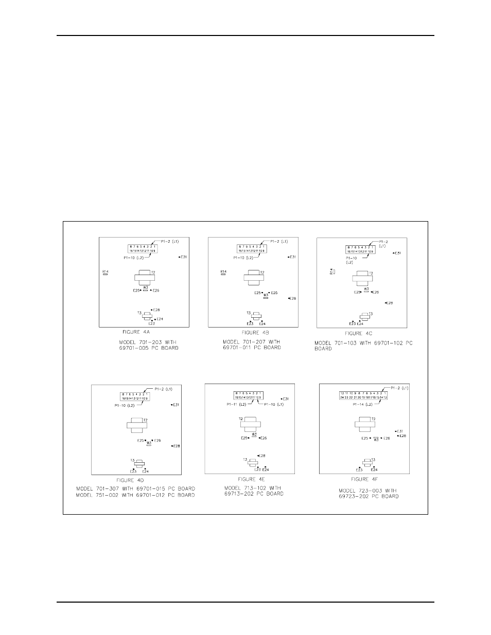
13. Wire connections from the VLC are to be soldered to the PCBA. See applicable model and PC board
in Figure 4.
N
OTE
: “E” locations may vary slightly from what is shown in Figure 4; however, the connections
remain the same.
Black E28
Red E31
Brown E24
White E26
Green E23
Yellow E25
Red/Blue
P1 (L1) Refer to applicable model and PC board in Figure 4.
Blue/Red
P1 (L2) Refer to applicable model and PC board in Figure 4.
14. Replace the PCBA by inserting the amphenol connector in the chassis opening and pressing it into
place. Push the standoffs through the chassis, and retighten the two screws holding the amphenol
connector to the chassis.
Figure 4. Wiring Details