GAI-Tronics 12250-004 Volume Level Control Receiver Assembly (24 V dc) User Manual
Page 4
Pub. 42003-204A
M
ODEL
12250-004
V
OLUME
L
EVEL
C
ONTROL
R
ECEIVER
A
SS
’
Y
(24
V
DC)
R
EPLACEMENT
K
IT
Page:
4 of 6
\\s_eng\gtcproddocs\standard ioms - current release\42003 kit manuals\42003-204a.doc
06/04
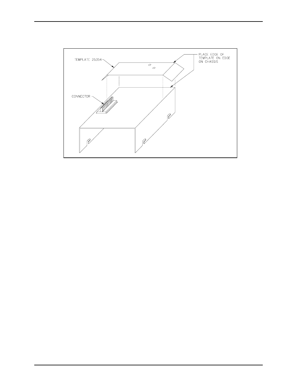
7. Turn the chassis over. With the connector opening at the top of the chassis, place the template along
the right edge of the chassis as shown on the diagram. Refer to Figure 3 below.
8. With the template in place, carefully center punch the holes. Drill two
5
/
32
-inch holes, and deburr the
opposite side.
9. Orient the PCBA with the connector at the top.
N
OTE
: Step 10 is applicable for models that have R14 installed in the off-hook detection circuitry.
See applicable models and associated boards in Figures 4A, 4B, and 4C for listing.
10. Replace R14 by de-soldering and removing the old resistor (10,000 ohm, ¼ watt, 5%
[brown-black-orange-gold]). Insert the 4,700-ohm, ¼-watt, 5% (yellow-violet-red-gold] resistor
provided in this kit into the PCBA, and re-solder it. Trim the resistor leads to avoid possible shorts
after re-assembly. See Figure 4.
11. De-solder and remove the W-3 jumper (0-ohm resistor) between E25 and E26. See applicable model in
Figure 4.
12. Remove solder from the following pads with a solder remover tool. If a solder remover tool is not
available, use a solder wick to remove the solder: E23, E24, E25, E26, E28, and E31.
N
OTE
: P1 connections do not require removing the solder. Heat the pin with the soldering iron, and
push the wire in.
Figure 3. Template 25354