Installation, Mechanical, Electrical – GAI-Tronics XCP00600A Navigator Output Control Module Kit User Manual
Page 2
Pub. 43003-034B
Model XCP0600A Navigator Output Control Module Kit
Page: 2 of
6
\\s_eng\gtcproddocs\radio products-current release\43003\43003-034b\43003-034b.doc
09/08
Installation
Mechanical
The XCP0600A Output Control Module Kit is provided with a 25-foot DB9-to-RS-485 cable for
connection between user-provided PC and the Model 12584-xxx Output Control Module. This cable can
be spliced to extend this connection to a maximum of 5000 feet using standard telephone wire.
Mount the 12584-xxx to any wooden or prepared metal surface (pilot holes are required) using the #8
×
3/4-inch screws provided with the kit.
Electrical
Wiring
WARNING
Do not apply power until all the connections have been wired.
WARNING
Connect only to a UL-listed Class 2 power source.
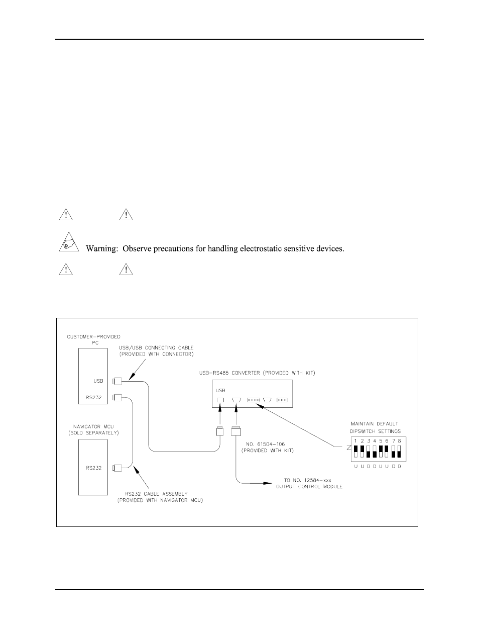
Please review Figure 1, the typical interconnection diagram, prior to beginning the installation.
Figure 1. Typical Installation Block Diagram