GAI-Tronics XCP00600A Navigator Output Control Module Kit User Manual
Page 3
Pub. 43003-034B
Model XCP0600A Navigator Output Control Module Kit
Page: 3 of
6
\\s_eng\gtcproddocs\radio products-current release\43003\43003-034b\43003-034b.doc
09/08
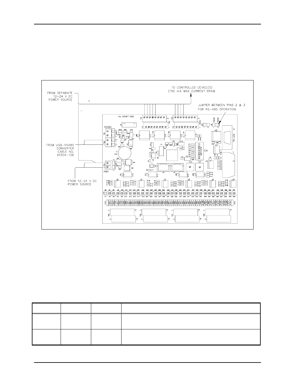
Data Connections
The Output Control Module supports both RS-485 and RS-232 data connections. A jumper (J6) is
provided to select either RS-485 or RS-232 data communications. Make certain that jumper J6
(located next to the RS-232 connector) is positioned between pins 2 and 3. Refer to Figure 2. The
RS-485 data connections are made directly to TB2, terminals 1 and 2. It is not required to observe
polarity.
Digital Output Connections
The TB10 and TB9 connectors each provide 16 digital (common ground) output connections designed to
drive externally-mounted relays or other indicating circuits. Each output can sink up to 150 mA of the
current. External circuitry (relays, indicators, etc.) must be powered from an external power supply of the
same voltage used to power the Output Control Module (12 to 24 V dc), or from the same actual source.
The ground (or dc common) terminals of the external power supply must be tied to TB4-2 if two
individual power sources are used. Refer to Figure 2.
Table 1.
Terminal Labeled Function Type
TB10-1 to
TB10-16
O
UT
-1
TO
16
Digital
output
Idle = +V dc, active (low) = sink100 mA maximum
TB9-1 to
TB9-16
O
UT
-17
TO
32
Digital
output
Idle = +V dc, active (low) = sink100 mA maximum
Each output corresponds with the same number control push button on the Navigator Control Screen.
Figure 2. Model 12584-xxx Output Control Module