GAI-Tronics XCP00600A Navigator Output Control Module Kit User Manual
Page 5
Pub. 43003-034B
Model XCP0600A Navigator Output Control Module Kit
Page: 5 of
6
\\s_eng\gtcproddocs\radio products-current release\43003\43003-034b\43003-034b.doc
09/08
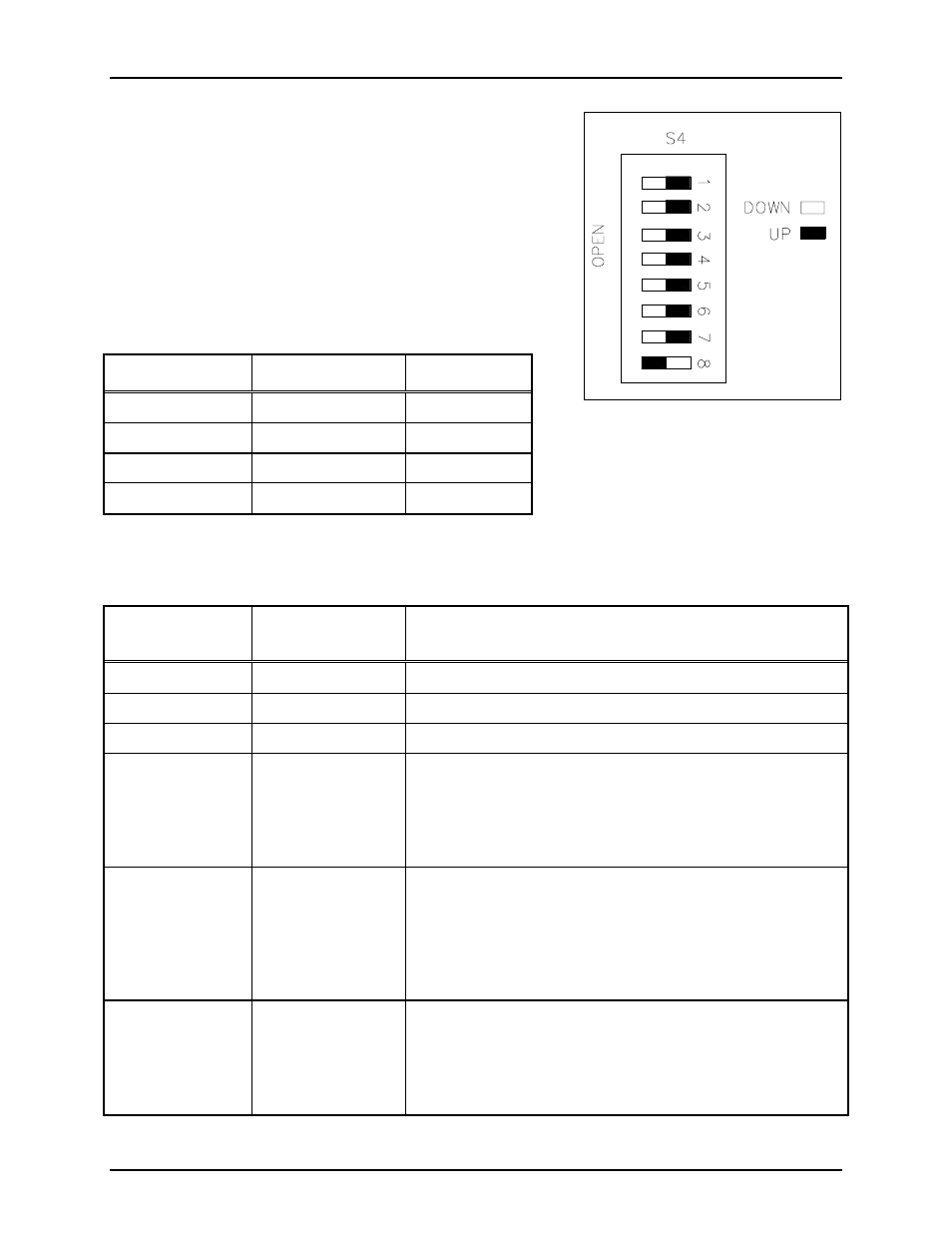
DIP Switch S4
An 8-position DIP switch S4 sets the various data parameters
and operation parameters of the I/O Controller.
Refer to Figure 5.
The following tables indicate each switch position and the
corresponding settings/functions. DIP switch S4 positions
1-2 set the serial data line baud rate as follows:
Table 4.
DIP Switch S4 Positions 1–2: Baud Rate
Switch S4-1
Switch S4-2
Baud Rate
Closed Closed 2400
Open Closed 4800
Closed Open
9600
Open Open 19200
Table 5.
DIP Switch S4 Positions 3–8: Operating Parameters
DIP Switch
Position
Function
Settings
S4-3
None – Not used
N/A
S4-4
None – Not used
N/A
S4-5
None – Not used
N/A
S4-6
Automatic input
response
Closed – will wait for a poll request from master controlling
device before sending an input activation data message.
Open – will automatically send a data message when an
active input is detected. The controller will NOT wait for
poll request from the master controlling devise.
S4-7 Address
return
Closed – will NOT return the controller’s address (set by hex
switch S1 and S2) when sending a data message to the master
controlling device.
Open – will return the controller’s address (set by hex switch
S1 and S2) when sending a data message to the master
controlling device.
S4-8
Data default
indication
Closed – if data communication is lost with the master
controlling device, all outputs will remain in their current
state until data communication is restored.
Open – if data communication is lost with the master
controlling device, all outputs will flash on/off.
Figure 5. DIP Switch S4