Siemens #6 instructions, Dampers with a jackshaft, Dampers without a jackshaft (shaft extension) – Greenheck 331-2856, 332-2856 - Siemens 6 Actuator (454206) User Manual
Page 2
These installation instructions assume the damper is already
mounted in a duct or sleeve with the damper shaft extending
beyond the duct or sleeve 6 inches.
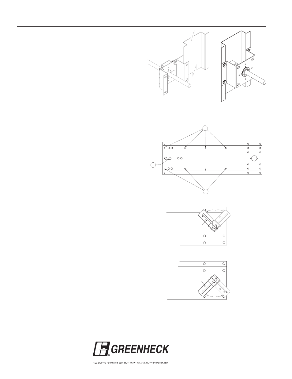
1. Install the stand off bracket.
Dampers with a jackshaft
1a. Mount the stand off bracket, #15, onto the jackshaft
bracket with (4)
1
/
4
-20 X
1
/
2 in.
thread cutting screws, #16.
Orient the bracket perpendicular to the damper on the duct
or sleeve so that the bracket shaft hole is centered on the
jackshaft.
Dampers without a jackshaft (Shaft
Extension)
1b. Mount the stand off bracket spanning across the damper
frame flanges with (4) #14 Tek screws, or equal, supplied by
others. Orient the bracket perpendicular to the damper on
the duct or sleeve so that the bracket shaft hole is centered
on the shaft extension.
Be sure not to run the screws into
the damper linkage, which is between the flanges.
2. Attach the auxiliary bracket, #17, to the mounting bracket
into two of the 6 holes label "B" to the right with (2) #10 Tek
screws, #17, supplied.
3. Mount the mounting bracket to the stand off bracket using
(4)
1
/
4
-20 x
1
/
2
in. bolts, #11, and (4)
1
/
4
- 20 Spinlock nuts,
#12, included with this kit. Use the outer four holes of the
mounting bracket for jackshafted models and the inner four
holes for directly driven models.
4. If the damper shaft has a diameter of
1
/
2
in., mount the roller
bearing to the mounting plate using (2) #10 Tek screws
supplied. If the damper shaft is 1inch in diameter, discard
the roller bearing.
5. Assemble the mounting post, #3, to the mounting bracket,
#13, with the (2)
1
/
2
in.-20 hex nuts, #4, supplied. Use the
hole illustrated “A" below.
6. Fasten the auxiliary bracket to the duct using (2) #10 Tek
screws (#17) provided.
7. Locate the center of the hole of the clevis approximately 4
inches away from the face of the actuator.
8. Mount the actuator to the post using two E-rings supplied.
9. Note the damper shaft rotation for fail direction and orient
the linkage appropriately. Position the crankarm in one of the
positions shown in the illustrations to the right.
9. Attach the crankarm to the clevis on the actuator with the
clevis pin and the hitch pin supplied through hole "C" shown
to the right.
10. Run the supply pressure to the actuator and regulate it to a
maximum of 25 psi.
11. Apply air pressure to the actuator. The damper blades
should fully open or close and return to the fail position
when air pressure is disconnected, if they do not,
adjustments can be made by changing the distance from
the actuator face to the center of the hole in the clevis.
A
B
B
C
90
Fail
Power
C
90
Fail
Power
Orientation of Stand Off
Bracket for a directly
driven damper
Orientation of Stand Off
Bracket for a jackshaft
driven damper
Crankarm orientation for counterclockwise fail rotation
Crankarm orientation for clockwise fail rotation
Copyright © 2014 Greenheck Fan Corporation
454206 Siemens #6 Rev. 5 September 2014
Siemens #6
Instructions