Greenheck Furnace PVF 4:1 Modulating Valve (474047) User Manual
Supplementary information
®
Supplementary Information
®
Part #474047
Furnace Models PVF and PVG
4:1 Modulating Valve
1
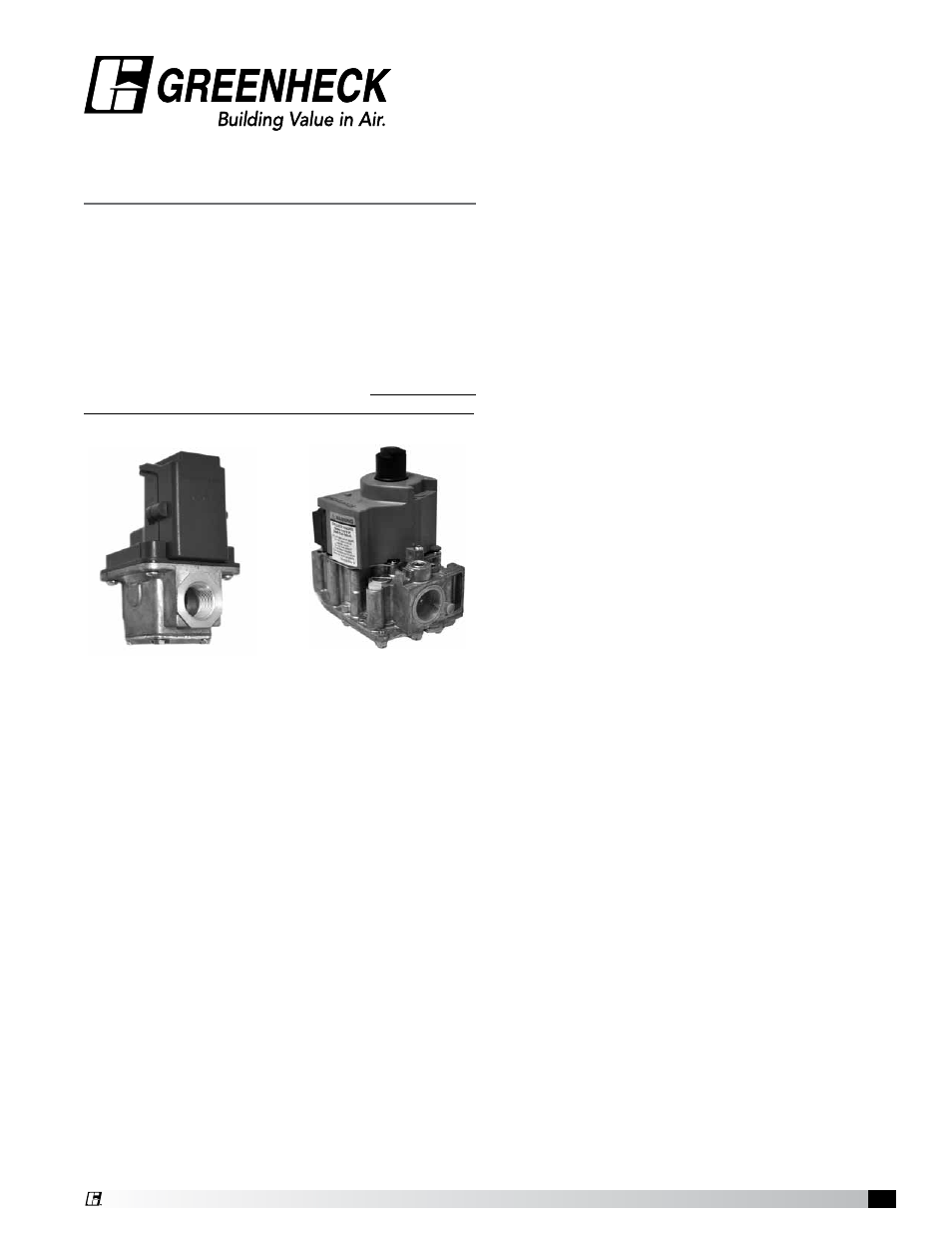
4:1 Modulating Valve
Typical EXA
Modulating Gas Valve
Typical Honeywell
Combination Valve
This unit is equipped with a model PVF or a
model PVG indirect gas-fired furnace that has a
4:1 turndown. The primary gas control valve used
in these units is a Honeywell combination valve. It
controls the high fire gas supply and acts as an on/
off switch. In addition to the Honeywell valve, there is
a Maxitrol EXA valve located just after the Honeywell
combination valve and the EXA valve is the device
that modulates or changes the gas volume that is
being supplied to the furnace manifold. Both of these
valves require adjustment at time of unit start-up.
The EXA gas valve has a built-in digital controller that
will accept user settings for High Fire and Low Fire
and will provide minimal hysteresis throughout the
entire range of modulation. The EXA valve controls the
amount of combustion gas that goes to the burners,
while the Honeywell valve acts as an on/off switching
device. During normal use, the amount of combustion
gas will vary constantly, depending on the settings put
in by the owner. This allows the EXA valve to regulate
the heat output from the furnace and maintain a
constant space temperature with minimal variation, or
hysteresis.
The EXA Modulating Valve is controlled by a
user interface known as the FX05 Controller,
manufactuered by Johnson Controls. The FX05
Controller sends an analog signal to the EXA
modulating valve that causes the valve to send more
or less gas to the furnace.
The Honeywell combination valve is normally closed.
It requires 24 VAC to hold it open.
Both the EXA and Honeywell gas valves have been
set at the factory for ideal operating gas pressures.
Vibration during shipment of the unit and field
conditions require that both valves be readjusted at
the time of start-up.
At start-up,
• Set the regulator screw on the Honeywell
combination valve as high as it goes (all the
way in).
• Set the High Fire set point on the EXA valve to
3.5 inches WC for natural gas or 10.0 inches WC
for LP gas.
• Set the Low Fire set point on the EXA gas valve
at 0.3 inches WC for natural gas or 1.0 inch WC
for LP gas.
The Maxitrol EXA valve has four electrical connections
on board. Two are for the 24 VAC needed to power the
valve and two are for the input signal from the FX05
controller. The location of the 24 VAC power source
varies, see the unit-specific wiring diagram. The
input signal that causes the EXA valve to change gas
volume is always provided by the FX05 Controller and
varies from 2 – 10 VDC.
When a call for heat is provided to the FX05 Controller,
the controller will provide a 10 VDC signal to the EXA
valve so that it will always start in a high fire condition.
After ignition, the controller will change its output
signal, causing the volume of combustion gas to be
reduced to as little as 25% of full flow (4:1 turndown).
For every installation of these gas-fired furnaces, it
is necessary to set the High Fire and the Low Fire
settings on the EXA valve. This is a simple process
that must be done in the field after the rest of the unit
is operational. To enter the High Fire and Low Fire
settings, it is necessary to have access to the on-
board printed circuit board in the EXA valve and to be
able to observe the LED indicator light on the circuit
board.
Remove the cover from the circuit board housing
by loosening the two Phillips head retaining screws.
Identify button #1, button #2 and the LED indicator
light. (see photo on other side of this document)