Greenheck Grille Installation Supplement (463622) User Manual
Installation instruction supplement, Figure 1 - metal stud figure 2 - wood stud
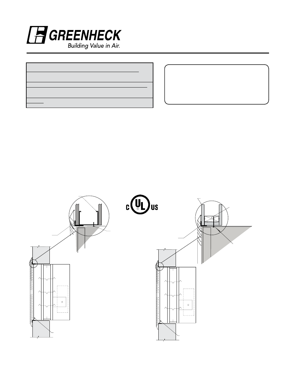
Grille (supplied
by others)
Steel stud
Retaining Angles
(See Section 2)
#10 2 1/2 in. long sheet metal
screws spaced 6 in. on center
and maximum of 2 in. from
the corners (minimum of 2
screws per side) through the
sleeve into the header, sill
and jamb framing members.
Screw into rear portion of the
studs so as to avoid space
conflicts with the grille
assembly.
Document number 463622
DFD, FD, FSD Series
Grille Installation
Installation Instruction Supplement
Refer to:
‘Installation Instructions for FD, DFD, SSFD Models Fire’
(Part #452763)
‘Installation Instructions for FSD-XXX, DFD-XXX, CFSD-XXX, &
SSFSD-XXX, Series Fire & Combination Fire Smoke Damper’
(Part #461336)
‘Installation Instructions for FD & DFD 150X Series Curtain Fire
Damper’ (Part #453946)
“UL CLASSIFIED
(see complete marking on product)”
“UL CLASSIFIED to Canadian safety standards
(see complete marking on product)”
Standards UL555 & UL555S
Classifications filed at UL under Listing #R13317
Clearance Requirements
There is no minimum clearance requirement between the wall opening and the sleeve exterior. However, to
facilitate installation, clearances between the wall opening and the damper sleeve are recommended. Although
there is no maximum allowable clearance, a minimum overlap of 1/2 in. (13mm) between the wall and the flange/
retaining angle must be maintained.
1. Single Flange Method
Damper/sleeve assemblies must be installed in wall openings using flanges and sheet metal screws as illustrated
and describe below. This method is only applicable to 11/2 hour rated damper; the 3 hour damper and dampers
larger than 36 in. x 36 in. (914mm x 914mm) will require a minimum of 11/2 in. x 11/2 in. (38mm x 38mm) legs.
• Flange on front (grille end) of sleeve must be a minimum of 16 ga. (1.6mm) steel and have a 5/8 in. minimum
flange leg. Using #10 sheet metal screws, screw from inside of sleeve through the rear portion of the studs (as
shown in Figure 1 & 2). Space screws a maximum of 6 in. (152mm) on center and a maximum of 2 in. (51mm)
from the corners (minimum of two screws per side). No retaining angles are required on the side of wall opposite
from the grille.
Figure 1 - Metal Stud
Figure 2 - Wood Stud
Grille (supplied
by others)
Retaining Angles
(See Section 2)
Gypsum Wallboard
Stud or Runner
In wood stud construction,
gypsum wallboard must cover
all wood stud surfaces.
#10 sheet metal screws, 2 1/2
inches long, spaced 6 in. on
center and maximum of 2 in.
from corners (minimum of 2
screws per side). Screw into
rear portion of the studs so as
to avoid space conflicts with
the grille assembly.
®