Greenheck Hinge Kit Sizes 220-540 (462865) User Manual
Installation, operation and maintenance manual, Installation
Installation, Operation and Maintenance Manual
Please read and save these instructions for future reference. Read carefully before attempting to assemble,
install, operate or maintain the product described. Protect yourself and others by observing all safety
information. Failure to comply with instructions could result in personal injury and/or property damage!
1
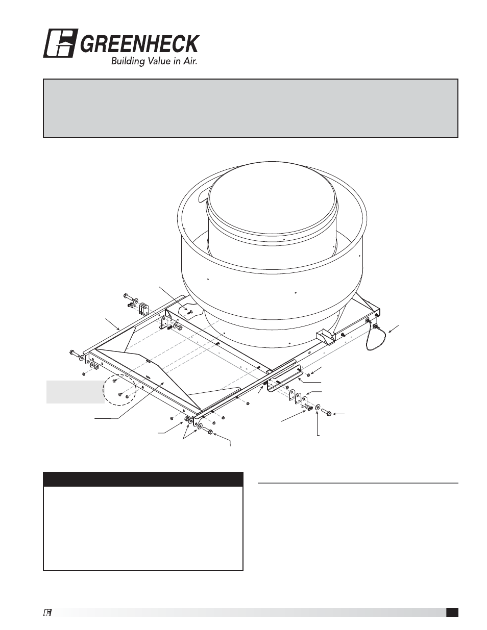
Hinge Kit
Installation
1. Step 1, remove bolts/screws from fan unit that will
be used to connect the reinforcing assembly plate.
FIGURE 1.
If fan is currently installed on a curb, remove screws
holding the cap to the curb. If this does not apply
go to Step 2.
FIGURE 1
WARNING
Disconnect power and observe proper lock out tag
out procedures per OSHA regulation (Title 29 code of
federal regulations part 1910.147 & 1910.333).
Note: If fan is connected to electrical source via rigid
connection, a qualified electrician will need to change
the rigid connection to a flexible connection long
enough per local electrical codes to allow for fan
movement.
Fan
Weld Bolt
5/16-18 x 1
Restraining
Cable
Bolt 1/2-13 x 2
Flat Washer
1/2 x 1-1/16
Flat Washer
1/2 x 1-1/16
Bolt
1/4 x 20 x 1¼
Nut
1/4-20
Curb Cap
Nut 1/2-13
Nylock
Nut 5/16-18
Top Hinge
Bottom Hinge
Hinge Spacer(s)
Bolt 1/2-13 x 2
Reinforcing
Assembly Plate
Step 1:
Remove from fan
unit and reuse
Document 462865
Hinge Kit
G/GB - Sizes 220-540
CUE/CUBE - Sizes 220-480
®
®