Greenheck HPR Series Adjustment on Pressure Relief Dampers (469134) User Manual
Hpr series, Flow damper blade
The following instructions should be followed when
attempting to modify HPR series pressure relief
dampers for different damper orientations or start-
to-open pressures. Dampers shipped are set for the
specified start open pressure and flow direction.
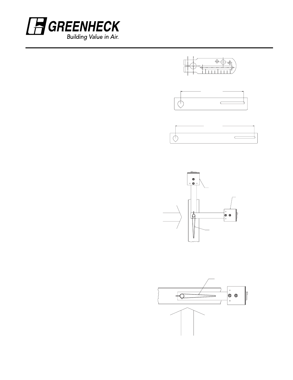
Pressure relief dampers designed for horizontal flow
(vertical mounting) are equipped with two sets of arms
(Figure 2A). The first set is in the direction opposite
the blades and offset, or balance, the weight of the
blades. The second set of arms is always positioned
horizontally when the damper is closed (approximately
vertical with blades open) and hold the blades closed
until the start-open pressure is reached. Pressure
relief dampers with vertical up flow/relief (Figure 2B)
and vertical down flow (Figure 2C) only have one set
of arms, as the weight of the edge pivoted blades is
either added or subtracted from the weight necessary
to hold blades closed.
Damper will respond to a positive differential pressure
in the direction of blade opening,
Three (3) different crankarms may be used, depending
on damper size and magnitude of start open pressure.
See Figure 1.
The blades of this type damper exhibit a gradual “lift
off” as start-open pressure is reached. The operating
point is not sharply defined, as when a door suddenly
opens. There is a wide flow range where pressure is
approximately constant.
Counterweight Set Procedure (Horizontal
flow only)
The counterbalance weights on a vertically mounted
damper (horizontal flow), must be adjusted first,
if the airflow direction is changed. This is covered
by a separate procedure. Basically, the damper is
adjusted for easy operation (blade weight is just
counterbalanced) before the pressure set arms and
weights are added.
Pressure Setting Procedure
Position damper in the proper orientation and flow
direction.
If a specific relief pressure is required, install a U-tube
manometer or other pressure measuring device in the
duct work to monitor the static pressure
.
If damper flow direction must be changed in the field,
loosen fastener in pressure set crankarm and rotate
arms to correct position. See Figures 2A, 2B and 2C
for correct pressure set arm orientation with damper
blades closed.
HPR series
Instructions for Adjustment on
Pressure Relief Dampers
Document number 469134
2
1
3
12 1/2 in. (318mm)
8 1/2 in. (216mm)
Figure 1
Small crankarm
Medium crankarm
Large crankarm
FLOW
DAMPER BLADE
COUNTERBALANCE
PRESSURE SET
Figure 2A Horizontal Flow
FLOW
DAMPER BLADE
Figure 2B Vertical Up Flow
®