Smdr-xxx and sssmdr-xxx blade orientation – Greenheck Leakage Rated Smoke Dampers - SMD, SMDR, SSSMD Series (461338) User Manual
Page 3
3
RATINGS
Integral Switch Type: Single Pole, double throw
Electrical:
10 Amps,
1
/
3
hp, 120 or 240 Vac
1
/
2
Amp, 120 Vdc;
1
/
4
Amp 240 Vdc
5 Amps, 120 Vac “L” (lamp load)
1.0 Amps, 24 Vac
1.5 Amps, 24 Vdc
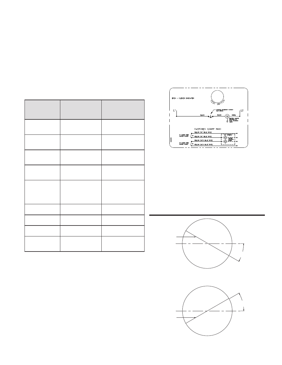
Fig. 2 OCI Wiring
Damper model
Maximum Single
Section Size
in. (mm)
Maximum Overall
Size for Multiple
Section Dampers
in. (mm)
SMD-201, 202,
203
36 x 48 or 32 x 50
(914 x 1219 or
813 x 1270)
144 x 100 or 288 x 50
(3658 x 2540 or
7315 x 1270)
SMD-201M, 202M
36 x 36
144 x 72 or 288 x 36
(3658 x 1829 or
7315 x 914)
SMD-301, 302
32 x 50
(813 x 1270)
128 x 100 or 256 x 50
(3251 x 2540) or
(6502 x 1270)
SMD-301M, 302M
32 x 50
(813 x 1270)
128 x 100 or 256 x 50
(3251 x 2540) or
(6502 x 1270)
SMD-401
48 x 60
(1219 x 7315)
192 x 120, 48 x 288,
or 384 x 36
(4877 x 1829,
1219 x 7315 or
9754 x 914)
SMDR, SESMDR,
SSSMDR
24
(610)
NA
SESMD-201,
SSSMD-201
24 x 30
(610 x 762)
88 x 72
(2235 x 1829)
SMD-301V
50 x 32
(1270 x 813)
100 x 32
(2540 x 813)
SMD-401M
36 x 36
(914 x 914)
144 x 72 or 288 x 36
(3658 x 1829 or
7315 x 914)
3. ATTACHING DAMPER TO THE DUCT
Attach the damper to the duct using #10 sheet metal
screws,
1
/
4
in. (6mm) diameter bolts and nuts, tack or
spot welds, or
3
/
16
in. (5mm) diameter steel pop rivets.
Attachments must be made at each flange spaced a
maximum of 6 in. (152mm) on centers and a maximum of
2 in. (51mm) from corners on rectangular dampers, and on
round dampers as follows: Ducts 22 in. (559mm) in diameter
and smaller shall have three attachments. Ducts larger
than 22 in. (559mm) in diameter up to and including 36 in.,
(914mm) have five attachments.
4. INSTALLING MULTIPLE DAMPER SECTION
ASSEMBLIES
The damper assembly is not restricted to a maximum
number of sections, but must not exceed the section sizes
and assembly sizes shown below.
The damper sections must be attached together with #10
sheet metal screws,
1
/
4
in. (6mm) diameter nuts and bolts,
1
/
2
in. (13mm) long welds, or
3
/
16
in. (5mm) diameter steel
pop rivets.
On multiple section damper assemblies, the temperature
rating of wiring run in the airstream shall be at least equal to
the damper temperature rating plus 50°F (10°C).
5. SEALING THE INSTALLATION
After installing the damper in the ductwork, seal the joint
between the damper frame and the duct using Dow Corning
RTV 732 sealant, GE1200 series silicone construction
adhesive or Component Hardware SLT-5000 silicone
sealant. Make sure to press the sealant into the joint to
guarantee a proper seal. Use the minimum amount of
material required to completely seal the joint. See Figure 1.
6. ACTUATOR CONNECTIONS
Electrical and/or pneumatic connections to damper
actuators should be made in accordance with wiring and
piping diagrams developed in compliance with applicable
codes, ordinances and regulations.
7. CONNECTION AND OPERATION OF OPEN/CLOSE
INDICATOR
OCI - The OCI (open or closed indicator) option contains
a single pole, double throw switch used to indicate
the damper blade position. The switch provides
a positive open or closed signal when used in
conjunction with remote indicator lights. Refer to Fig.
2 for wiring of the OCI option.
SMDR-XXX and SSSMDR-XXX Blade
Orientation
30° Off Horizontal
(Maximum)
Axle
30°
30° Off Horizontal
(Maximum)
Axle
30°