Greenheck Metal Stud in Shaftwall Partition Supplement (462100) User Manual
Fd, dfd,odfd, and ofd series, Fsd, ofsd and gfsd series, Dfdr, fdr, fsdr series
Document number 462100
Installation Instruction Supplement for
“UL CLASSIFIED (see complete marking on
product)”
“UL CLASSIFIED to Canadian safety standards
(see complete marking on product)”
Standard 555 (Listing #R13317)
Standard 555S (Listing #R13447)
Notes
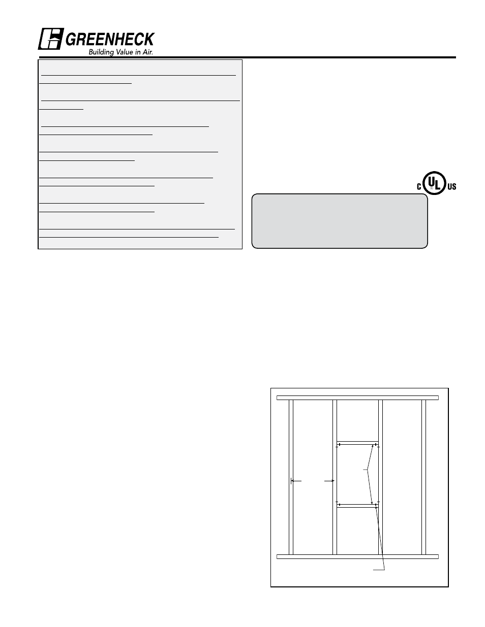
1. Gypsum panels must be screwed 12 in. (305mm) on center
maximum to all stud and runner flanges surrounding
opening. (See Figure 1 and Figure 2 for Opening
Preparation Details).
2. Fire damper and sleeve assemblies 80 in. W x 50 in. H
(2032mm x 1270mm), 50 in. W x 80 in. H (1270mm x
2032mm), or 40 in. W x 100 in. H (1016mm x 2540mm)
and smaller only require retaining angles on one side
of the partition (See Figure 3 and Figure 4). Retaining
angles must be attached to the sleeve and the partition.
Larger damper assemblies require retaining angles on
both sides of the partition. Retaining angles must be
attached to the sleeve.
• Retaining angles for 11/2 hour rated dampers with a width
and height 48 in. (1219mm) or less must be a minimum
of 20 ga. (1mm). Retaining angles for all 3 hour rated
dampers and all dampers with a width or height greater
than 48 in. (1219mm) must be a minimum of 16 gauge
(1.5mm). The leg of the retaining angle on the damper
sleeve shall be a minimum of 11/4 in. (32mm). The leg of
the retaining angle on the wall/floor shall be long enough
to cover the annular space and overlap the wall/floor by
at least 1 in. (25mm).
• Retaining angles must be attached to the partition and
sleeve using one of the methods shown below.
• tack or spot welds
• #10 sheet metal screws and bolts
• Drywall screws of a length such that the screw
engages the stud/track by a minimum of 1/2 in.
(13mm)
• A minimum of two connections per side, top, and
bottom, 12 in. on center maximum for openings of
48 in. W x 36 in. H (1219mm x 914mm) and less, and
6 in. (152mm) on center for openings 80 in. W x 50 in.
H (2032mm x 1270mm), 50 in. W x 80 in. H (1270mm x
2032mm), and 40 in. W x 100 in. H (1016mm x 2540mm)
or less.
Grille Installations (Dampers up to 36 in. x 36 in.
[914mm x 914mm] maximum)
Refer to:
‘Installation Instructions for FD, DFD, SSFD, SSDFD, & KFD
Series Curtain Fire Dampers’ (Part #452763)
or
‘Installation Instructions for FD and DFD 150X Series Curtain
Fire Dampers’ (Part #453946)
or
‘Installation Instructions for FSD and SSFSD Series
Combination Fire Smoke Dampers’ (Part #461336)
or
'Installation Instructions for DFDR, SSDFDR, FDR and
SSFDR Round Fire Dampers' (Part# 462721)
or
'FSDR-XXX, SEFSDR-XXX and SSFSDR-XXX Round
Combination Fire Smoke Dampers' (Part# 461868)
or
'GFSD-XXX Series Grille Access Out of Wall/Floor
Combination Fire Smoke Dampers' (Part# 472477)
or
'OFSD-XXX, ODFD-XXX, OFD-XXX and OSSFD-XXX Out of
Wall/Floor Combination Fire Smoke and Fire Dampers'
(Part # 461337)for additional details.
FD, DFD,ODFD, and OFD Series
1 1/2 Hour Curtain Fire Dampers and
FSD, OFSD and GFSD Series
1 1/2 hour Combination Fire Smoke Dampers
Vertical Mount
DFDR, FDR, FSDR Series
1 1/2 hour Round Fire and Combination Fire
Smoke Dampers and
Metal Stud Framing for Fire Dampers in
Cavity Shaftwall Partitions
• Angle legs may be reversed and one leg inserted into
the wall opening. Retaining angles used in conjunction
with grille installations must be a minimum of 20 gauge
(1mm) steel and have a minimum of
5
/
8
x 1 in. (16mm x
25mm) legs
(
See Figure 5 and Figure 6).
OR
•
Using #10 sheet metal screws, screw from inside of
sleeve into the studs.
Space screws a maximum of 6 in.
(152mm) on center and a maximum of 2 in. (51mm) from
the corners (minimum of 2 screws per side). (See Figure
7 and Figure 8).
3. These installation instructions apply to the following wall
design numbers as detailed in the UL Fire Resistance
Directory: U438, U469, U497,U499, V473 System A.
24 in. O.C.
Maximum
J-Runner
1
1
⁄
2
in. x 1
1
⁄
2
in. x 2 in. Min. angle
attached with
5
⁄
8
in. type #12
screws (min.)
Figure #1: Opening Preparation Detail
®