Greenheck Microprocessor Controller Start-Up Guide v3.0 (469710) User Manual
Microprocessor controller start-up guide
®
UNIT START COMMAND: For manual operation
jumper R to G on unit (BMS or Time Clock – refer to
Controller IOM) The controller will display a Start-Up
screen that shows the program version along with
the specifi c code for the unit. This code should be
verifi ed with the “DDC Setup Code”
on the unit’s
wiring diagram.
•
Outdoor air and Exhaust air (optional) damper
actuators are powered
•
Energy wheel is powered
•
Exhaust fan starts after a 15 second delay
•
Supply fan starts fi ve seconds after the
exhaust
fan.
UNIT STOP COMMAND:
For manual operation open R to G on unit (BMS or Time Clock – refer to Controller IOM)
•
Supply fan, exhaust fan are de-energized.
•
Wheel, outdoor air and exhaust air damper (optional) are de-energized and dampers spring return closed.
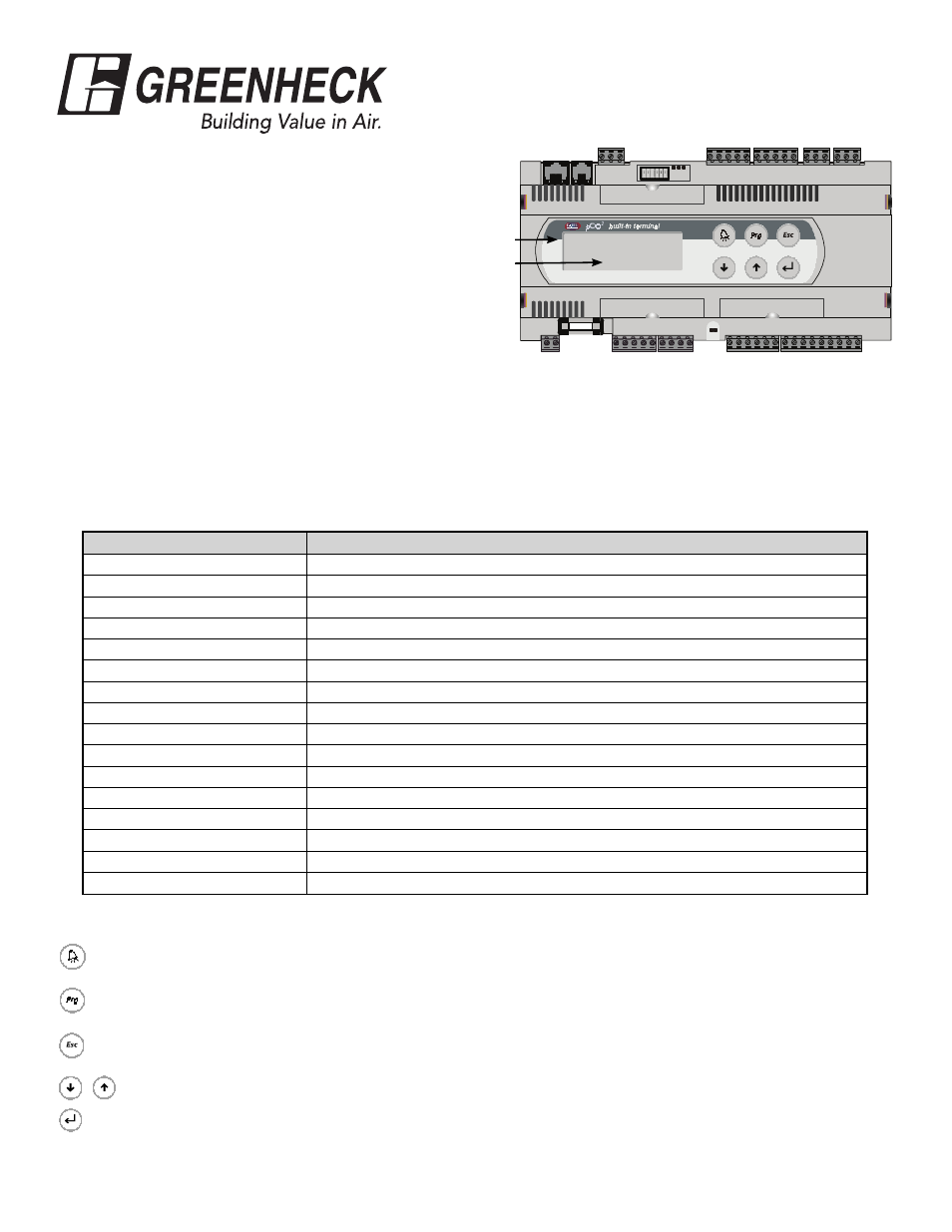
UNIT STATUS:
From the start-up screen, press the blinking ESC button
After approximately three minutes of inactivity the controller will display a “Unit Status” screen describing the real-time mode the
unit is operating in. Below is a description of operational sequences the unit could be executing
Initial Delay
Outside: 000.0 F
Supply: 000.0 F
Cold Coil: 000.0 F
G
GO
Wire Power to G and GO
Shows
Unit
Status
Displays
Temperatures
Part #469710
Microprocessor Controller
Start-Up Guide
Unit Status
Possible Operation Sequence
INITIAL DELAY:
15 second delay before dampers open
OPENING DAMPERS:
Dampers will open for programmed time (Default: 10 sec.), wheel energized
EXHAUST FAN STARTING:
Power to Exhaust Fan
SUPPLY FAN STARTING:
Power to Supply Fan SYSTEM ON: Startup Sequence is complete
DEFROST MODE ACTIVE:
Timed exhaust, preheat, or modulating wheel
SYS ON-ECONOMIZER:
Wheel ON/OFF or modulating to maintain discharge temperature
SYS ON-HEATING:
Unit heating to meet desired supply temperature
SYS ON-COOLING:
Unit cooling to meet desired supply temperature
SYS ON-DEHUMIDIFYING:
Unit cooling to meet desired post cooling-coil temperature
SYS ON-DEHUM & REHEAT:
Unit cooling to dehumidify-reheating to desired supply temperature
UNOCCUPIED-UNIT OFF:
Unit off during unoccupied mode
UNOCCUPIED-HEATING:
Unit heating recirculated air to maintain unoccupied room heating temperature
UNOCCUPIED-COOLING:
Unit cooling recirculated air to maintain unoccupied room cooling temperature
MANUAL OVERRIDE!!:
The system is in Manual Override operation
REMOTE OFF:
The unit has been turned off from a remote display panel
PRESS ALARM BUTTON!:
An alarm is occurring
CONTROLLER BUTTONS
In the event that the unit is not functioning normally, the alarm light will turn red. Press the button once to see which alarm
occurred. Press again for alarm options. Please refer to Controller IOM for more information on specifi c alarms.
The program button is used to setup the control loops, staging, passwords, etc. A qualifi ed technician should perform
adjustments to these parameters. (A level 2 password must be entered to alter any of the factory programming).
Escape button returns you to the main menu where the following menus can be accessed: Unit Status, Set Points, Manual
Overrides, I/O Setup, Clock Setup, Misc Info, and Unit On/Off.
Use the up and down arrow buttons to scroll through display screens, and to set the values of the control parameters.
Use the return button to confi rm the set data.
For additional information see the Installation and Operation Manual (IOM) shipped with this unit. If missing, contact the factory or
visit greenheck.com
#469710 Microprocessor Start-Up Guide
Rev. 1, February 2007
Copyright © 2007