Greenheck CUE (457692) User Manual
Read and save these instructions, Installation, operation and maintenance manual, Pre-starting checks
Model CUE Direct Drive
Upblast Centrifugal
Roof Exhaust Fan
Pre-Starting Checks
Check all fasteners for
tightness. The wheel
should rotate freely
and be aligned as
shown at right. Wheel
position is preset and
the unit tested at the
factory. However,
movement may occur
during shipment, and
realignment may be
necessary. Centering (height
alignment) may be
accomplished by loosening
the set screws in the wheel
and moving the wheel to
desired position.
Installation
Upon receiving unit, check for any damage and report it immediately to the shipper. Also check to see that all accessory items
are accounted for.
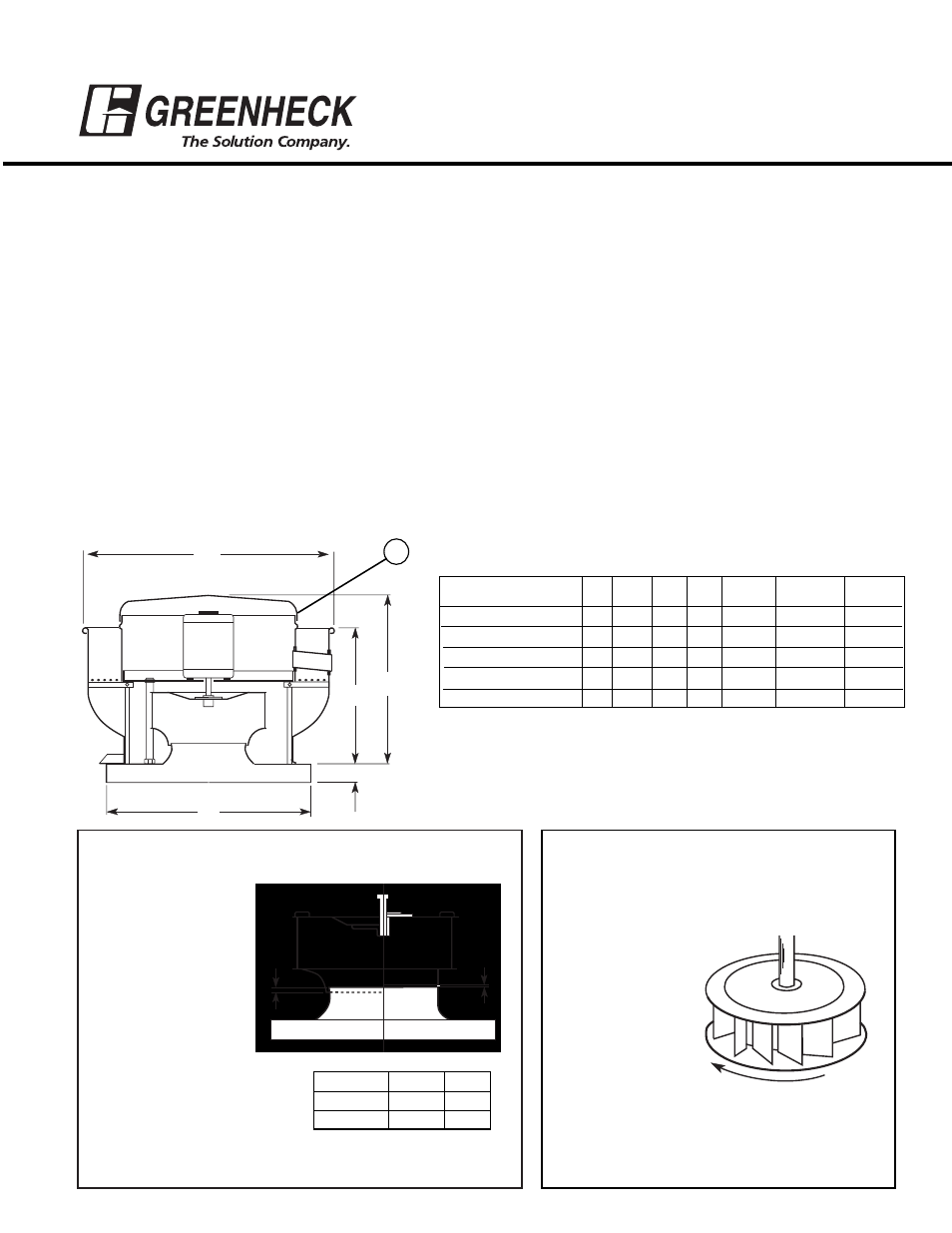
Move fan to desired location and fasten securely through mounting holes in base. Shims may be necessary depending upon
roofing material thickness. The diagram below shows dimensions for Model CUE.
Access to the motor compartment is accomplished by removing the screws designated “R” in the drawing below. The cover
can then be removed and placed on a flat surface in an area protected from strong winds that could blow it off the roof.
The voltage rating of the motor must be checked for compatibility to supply voltage prior to final electrical connection. For
NFPA - restaurant applications, the electrical supply must enter the motor compartment through the breather tube. For other
non-flammable applications, the electrical supply can be routed through the conduit chase between the curb cap and the
bottom of the motor compartment. Consult local code authorities for your specific requirements.
IMPORTANT: UL/cUL 762 Installations are for Restaurant Applications.
A, B, and C motor RPMs are only approved for this installation. All must include the suffix “G”.
A drain trough is provided on all CUE fans for one point drainage of residue. Some means of collection of this residue must be
provided by either placing a container directly under the trough or by utilizing an adapter to direct the residue to another
location.
B
C*
D
A
1
3
/
4
"
R
Dimension “A” is the inside dimension of the curb cap.
The roof curb should be 1-1/2" less than the curb cap to allow for
roofing and flashing.
*May vary depending on motor size.
Dimensional Data
Wheel Rotation
Direction of rotation is very critical. Improper
rotation will result in loss of performance,
excessive horsepower and possible motor
burnout. Check
rotation by
energizing the unit
only momentarily.
The rotation should
be as shown in the
diagram at right and
should be in the
same direction as
the rotation decals
affixed to the unit.
G
H
Fig. 1
Fig. 2
Clockwise
CUE Models 060-161
Roof
Approx.
Model
A
B
C
D Damper
Opening
Unit Wt.
CUE-060,065,070,075
17
18
3
/
8
13
1
/
2
11
3
/
8
8x8
10
1
/
2
x10
1
/
2
26
CUE-080,085,090
19
21
13
3
/
8
11
1
/
2
10x10
12
1
/
2
x12
1
/
2
33
CUE-095
19
21
15
1
/
4
13
7
/
16
10x10
12
1
/
2
x12
1
/
2
36
CUE-098,101,121,131
19
24
7
/
8
23
3
/
4
17
3
/
8
12x12
14
1
/
2
x14
1
/
2
67
CUE-141,161
22
28
7
/
8
24
3
/
4
19
3
/
8
16x16
18
1
/
2
x18
1
/
2
85
MODEL
G
H
060-095
-
3/32 in.
098-161
1/4 in.
-
®
READ AND SAVE THESE INSTRUCTIONS
PN 457692
Installation, Operation and Maintenance Manual