Greenheck MP-100A (463548) User Manual
Installation instructions
®
®
Document #463548
MP-100A Motor Pack
UL listed electric actuators with spring return
for use with WD-100 series dampers
Installation Instructions
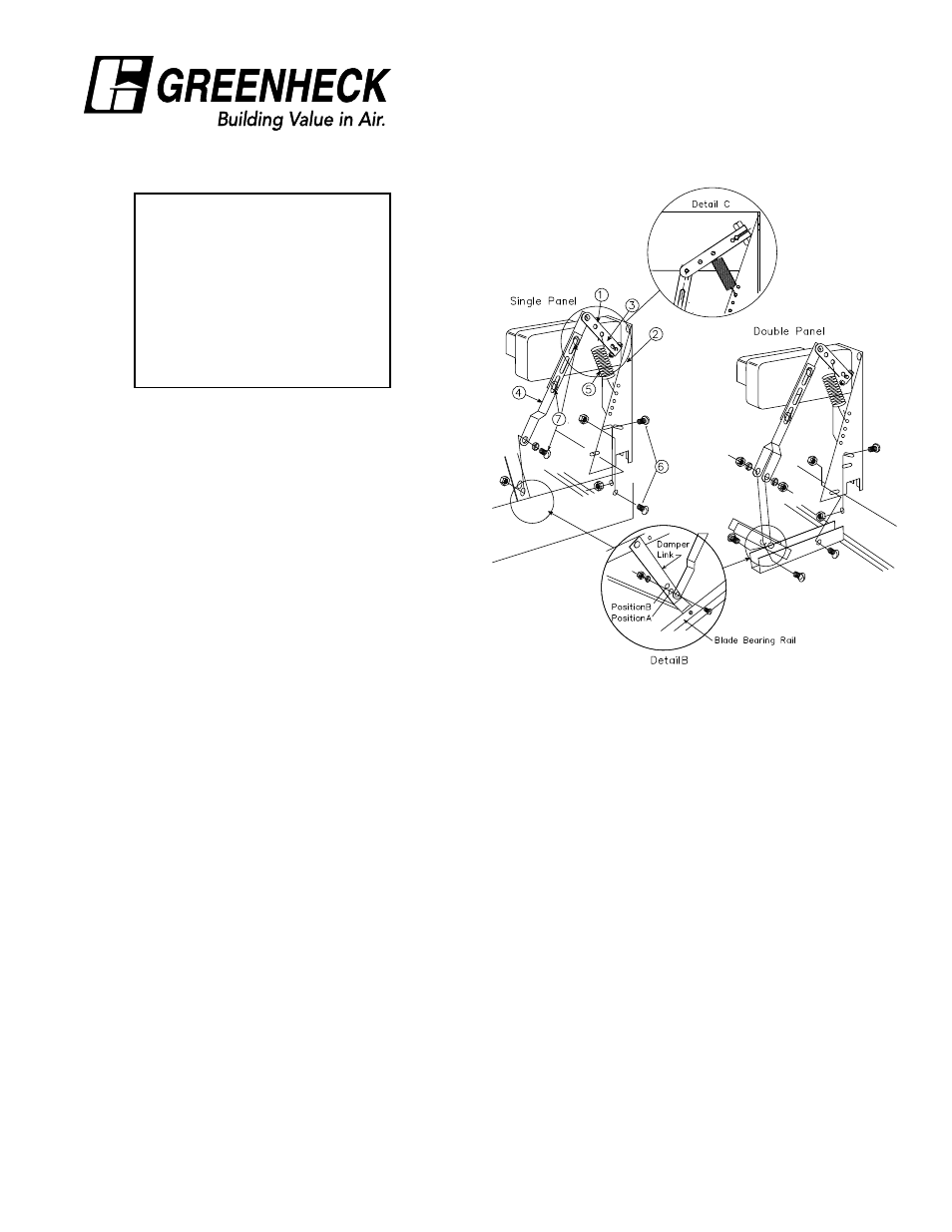
Motor Pack Contents
1. Actuator
2. Actuator Bracket
3. Actuator Arm Assembly
4. Connecting Links
5. Actuator Spring
6. 1/4-20 Screws and Nuts
7. #10 Screws and Nuts
All necessary hardware included
1. The MP-100A motor pack is designed for installation
on model WD-100 series backdraft dampers
only. When properly installed, the damper will be
horizontally mounted (air flow up) and the motor pack
will be above the damper.
2. Attach connecting link(s) to the damper link using
the #10 hardware along with the bronze bushing(s)
(see Detail B). Use position “A” on most applications.
Position “B” can be used on larger dampers when a
negative pressure is present. The damper blades can
be lifted to the open position to provide easier access
when attaching the connecting link(s) to the damper
link. Tighten all fasteners.
Note: Check that the connecting links are over the
bushing(s) and not pinched between the end of the
bushing and the screw or damper link. As the blades
are being closed, the linkage bolt that is used to
attach the connecting link to the damper link may
interfere with the damper blade bearing rail, causing
the blades to remain slightly open. To resolve this
interference issue, using pliers, bend that area of the
damper blade bearing rail away from the bolt head
until sufficient clearance is provided.
3. Attach the motor pack assembly to the damper
frame with the 1/4 in. hardware provided. Assemble
the connecting link(s) to the actuator arm assembly
using the #10 hardware. The damper blades should
be closed during this connection. The angle between
the connecting links and the actuator arm should
be as shown in Detail C with a slight tension on the
spring. Tighten the fasteners between the connecting
link and the actuator arm assembly. Fasteners
should be placed as far apart as possible. This will
provide greater stability to the linkage. Operate the
damper manually. Verify that the linkage fasteners do
not interfere with any components of the assembly
and that the damper blades close completely when
released.
Note: The spring can be adjusted to provide more
or less closing force. It is important not to use too
much spring tension; use just enough to help close
the damper. Too much tension could impair damper
opening.
To adjust the spring, unhook the spring from the
actuator bracket and reattach to the next hole that
provide more or less tension.
4. Actuators are supplied with junction boxes and
covers. When wiring, make sure the supply voltage
agrees with the actuator voltage. On dual voltage
motor packs, be sure to connect the proper motor
leads for the correct voltage and insulate any unused
wire. The voltage of each specific model is indicated
on a label that is affixed to the actuator (see page 2
and 3 for typical wiring diagrams).
5. If the damper fails to operate properly, check for one
of the following causes:
• Check for an ‘out of square’ or racked damper
• Check for mounting screws interfering with the
blade and linkage rotation
• Spring tension too great
• Excessive voltage drop
• Excessive negative pressure in the building
If the actuator fails to function:
• Check for correct voltage
• Check for proper wiring