Greenheck RL147 Positioner Relay User Manual
Page 8
Technical Instruction
Landis & Gyr, Inc.
RL 147-2
Page 8
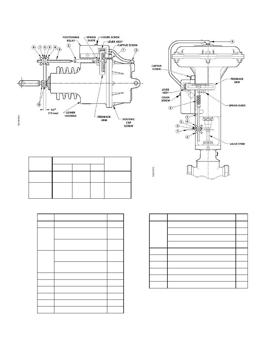
Figure 8. Positioning Relay Mounted
on the No. 6 Damper Actuator.
Table 7. Spring Selection for Adjustable Stroke
of the No. 6 Damper Actuator.
Actuator
Feedback Spring
Adjusting
Stroke
Color
Nominal
Max
Screw
3-1/4 to 4
(82 to 102)
Blue
4 (102)
4-1/4
(108)
4-1/2 (114)
long
2-29/32 to
3-1/4
(74 to 82)
Cadmium
3 (76)
3-1/4
(82)
1-3/4 (44)
long
Table 8. Mounting Kit 147-276
for the No. 6 Damper Actuator.
Item
Description
Q'ty
1
Mounting Bracket
1
2
Feedback Spring
4" (102 mm) stroke (blue)
1
Feedback Spring
3" (76 mm) stroke (Cad.)
1
3
Adjusting Screw
4-1/2" (114 mm) long
1
Adjusting Screw
1-3/4" (44 mm) long
1
4
Wing Nut
2
5
Lock Washer
1
6
Flat Washer
1
7
Spring Arm
1
8
3/8-24 Hex Nut
2
9
90° Elbow Connector
1
Figure 9. Positioning Relay Mounted on a
VP 591 8" Valve Actuator.
Table 9. Mounting Kit 147-333
for the VP 591 8" Valve Actuator.
Item
Description
Q'ty
Feedback Spring-Small Cad. Plate
2
Feedback Spring-Small Red
1
Feedback Spring-Large Green
1
Feedback Spring-Small Green
2
3
Adjusting Screw-4" (102 mm) long
1
4
Wing Nut
2
5
Lock Washer
1
6
Flat Washer
1
7
Spring Arm
2
9
90° Elbow Connector
1
2