Greenheck Temperature Limited Override TOR (471837) User Manual
Installation instructions for tor, On fsd, sefsd, ssfsd series, Temperature limited override)
Document number 471837
Installation Instructions
for TOR
(Temperature Limited
Override)
on FSD, SEFSD,
SSFSD series
Steps to install an TOR in a Fire Smoke Damper:
Upturned Leg Faces
Away From Blade End
#10 x 1/2 in. Tek Screw
or Equivelant
Part No. 415555
2 Req’d
0.166 in. dia.
2 Places
Indicator Bracket
Part No. 658594
1 Req’d
#10 x 1/2 in. Tek
Screw
or Equivelant
Part No. 415555
2 Req’d
Upturned Leg
Faces Away From
Blade End
Indicator Bracket
Part No. 658594
1 Req’d
1.625
1.750
Indicator Link
(short or long; see C)
1 Req’d
Push Nuts
2 Req’d
Gasket
1 Req’d
J-Box Cover
1 Req’d
#10-16 x 3/4 in
.
SIHWH Screw
2 Req’d
J-Box
1 Req’d
A
B
C
D
TOR
1 Req’d
Note: Indicator Link Part Nos
.
For Standard Sleeve (short): 457808
For Extended Sleeve (long): 457801
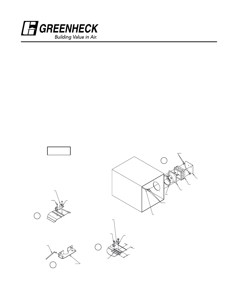
TOR - Exploded View
Airfoil Blade
3-V Blade
Indicator
Bracket
Indicator
Link
1) Drill/saw a 3
5⁄8
in. (92mm) diameter hole in sleeve
(Detail 2).
2) Attach indicator bracket to blade. For an airfoil
blade dampers, use existing holes in blade (Detail
1-A). For a 3V blade damper, drill two 0.166
in. (4mm) holes (Detail 1-B). Fasten bracket to
bladewith #10 x 1/2 in. (13mm) TEK screws (or
equilavent).
3) Fit indicator link into blade bracket (Detail 1-C).
4) Insert TOR unit through hoel in sleeve (round end
inside).
5) Place 4 in. x 4 in. J-box over the flange of the TOR
unit and align holes.
6) Mount control box to sleeve/sideplate with
#10-16 x3/4 in. (19mm) TEK screw or equilavent
(Detail 1-D).
7) Place one pushnut on the switch wire. Place
indicator link on switch wire and secure with a
second pushnut (Detail 1-D).
8) Complete wiring and install J-box cover.
Detail 1
®