Greenheck Tunnel Corridor Supplement (463832) User Manual
Cfsd series, 1 hour corridor ceiling fire smoke dampers
Refer to:
‘Installation Instructions for CFSD Series
Corridor Ceiling Dampers’ (Part #461335) for
additional details.
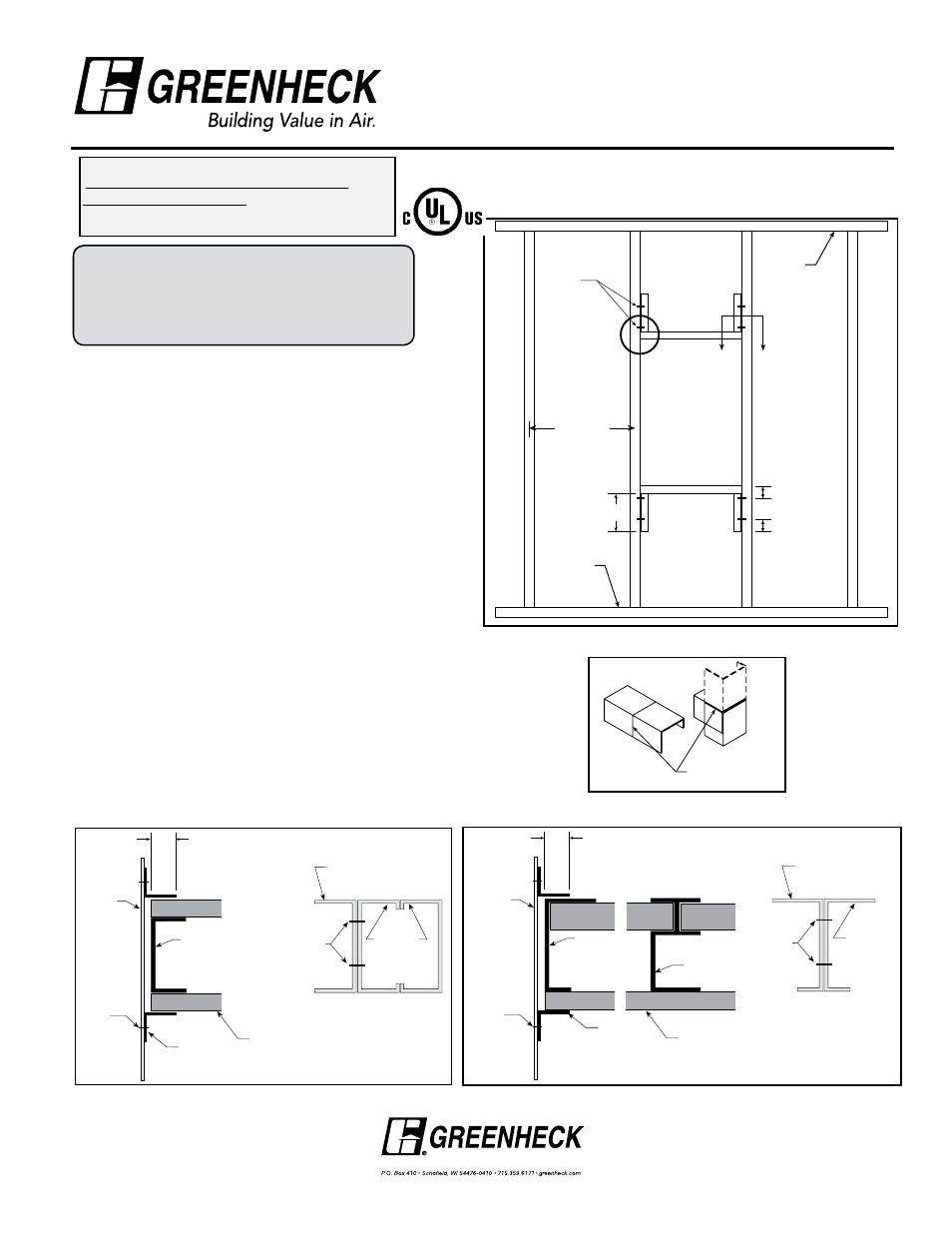
Detail ‘A’: Forming Channel
Figure #1: Opening Preparation Detail (top view)
Notes
1. Gypsum panels must be screwed 12 in. (305mm) O.C.
(on center) maximum to all stud and runner flanges
surrounding opening with 1
5
/
8
in. (41mm) drywall screws
or fasteners designated by the appropriate corridor
ceiling design. (See Figure 1 for Opening Preparation
Details).
2. Retaining angles must be attached to the sleeve (not the
partition). (See Figure 2 and 3.)
- Retaining angles must be a minimum of 20 gauge
(1mm) steel and have a minimum of 1
1
/
2
in. x 1
1
/
4
in.
(38mm x 32mm) legs.
- Retaining angles must be attached to the sleeve using
one of the methods shown below.
- tack or spot welds
- #10 sheet metal screws
-
1
/
4
in. x 20 bolts and nuts
-
3
/
16
in. (4.7mm) steel rivets
- Quick-Lock Joints
- A minimum of two connections per side, top, and
bottom (12 in. [305mm] on center maximum).
- Retaining angles must overlap the partition a minimum
of 1 in. (25mm)
- A minimum
3
/
4
in. x 20 gauge (19mm x 1mm) flange
termination may be used in lieu of retaining angles on
the corridor side of the damper sleeve.
Cut here and
bend down
Copyright © 2013 Greenheck Fan Corporation
463832 Tunnel Corridor Supplement Rev. 5 January 2013
24" O.C.
Maximum
Side
Runner
Detail ‘A’
Side
Runner
2”
2”
12”
A
A
Two
Panhead
Screws
“UL CLASSIFIED (see complete marking on
product)”
“UL CLASSIFIED to Canadian safety standards
(see complete marking on product)”
Standard 555, 555S (Listing #R13317)
Document Number 463832
INStALLAtION INStrUCtION SUPPLEMENt
CFSD Series
1 Hour Corridor Ceiling Fire Smoke Dampers
Metal Stud Framing for Fire Dampers in tunnel Corridor
Shaftwall Ceilings
Retaining
angle
5
/
8
" UL Classified Gypsum
Wallboard min.
20 ga. steel
stud
Damper
Sleeve
Angle
Fastener
(see Note 2)
1”
Min.
2
1
⁄
2
” min. stud
Screws
2
1
⁄
2
” min.
stud
Section A-A
Figure #2: 1 Hour Shaftwall rating (‘C’ Channel)
Retaining
angle
5
/
8
" UL Classified Gypsum
Wallboard min. (see UL
Rated Wall Design for
Additional Details)
20 ga. steel
J-Runner
C-H Stud
Damper
Sleeve
Angle
Fastener
(see Note 2)
1”
Min.
2
1
⁄
2
” 20 ga.
steel J-Runner
Screws
2
1
⁄
2
” min.
stud
Section A-A
Figure #3: 1 Hour Shaftwall rating (‘C-H’ Channel)
®