Greenheck Vari-Green Control - Universal Assemblies (475699) User Manual
Installation, operation and maintenance manual
®
Document 475699
Universal Vari-Green
®
Control Assemblies
Installation, Operation and Maintenance Manual
Please read and save these instructions for future reference. Read carefully before attempting to assemble, install,
operate or maintain the product described. Protect yourself and others by observing all safety information. Failure
to comply with instructions could result in personal injury and/or property damage!
Universal Vari-Green Control Assemblies
1
®
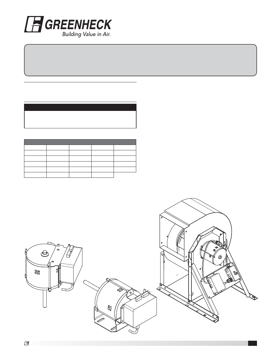
Side of Motor Mounting
(Fig. 1)
For use on G, CUE, CW, LD, and LDP units
• Fasten transformer to mounting bracket via
(4) supplied screws (#10 x 1/2).
• Bend top of bracket away from transformer, by hand,
along laser stitched line, forming a 90 degree angle.
• Attach bracket to top of motor via (2) motor thru-bolts.
Fasten down with supplied nuts.
NOTE
There will be extra hardware and parts included
with this kit that may not be used for your specific
application.
Section 1
Fig. 1
Fig. 2
This document is for transformer/2-speed control-
ler mounting only. Reference the Vari-Green Motor
Document No. 473681 for wiring details.
For Motor Part Numbers
309025
309026
310107
310306
310307
310359
311377
311388
311731
311812
312359
312360
312361
312362
312619
313233
313234
313235
314534
314945
316495
316496
316497
316498
316499
317706
317707
317708
317709
SWD-7 THRU 10
with transformer
and switch
End of Motor Mounting
(Fig. 2)
For use on SE/SS Sidewall Prop units and SFD units
• Fasten transformer to mounting bracket via
(4) supplied screws (#10 x 1/2).
• Attach bracket to end of motor via motor thru bolts.
Fasten down with supplied nuts.
• For a SFD make sure transformer is mounted under
weatherhood.
Fan Housing Mounting
For use on SQ units
• Fasten transformer directly to outside of unit via
(4) supplied screws (#10 x 1/2).
For use on SWD units
• Fasten transformer to Drive Frame Angles
using the pre-exisiting holes and the (4) supplied
screws (#10 x ½)