Vgn technology control flow chart - single fan, General electrical controls information – Greenheck Vektor Laboratory Exhaust with VGN Technology Electrical Controls Information (476072) User Manual
Page 5
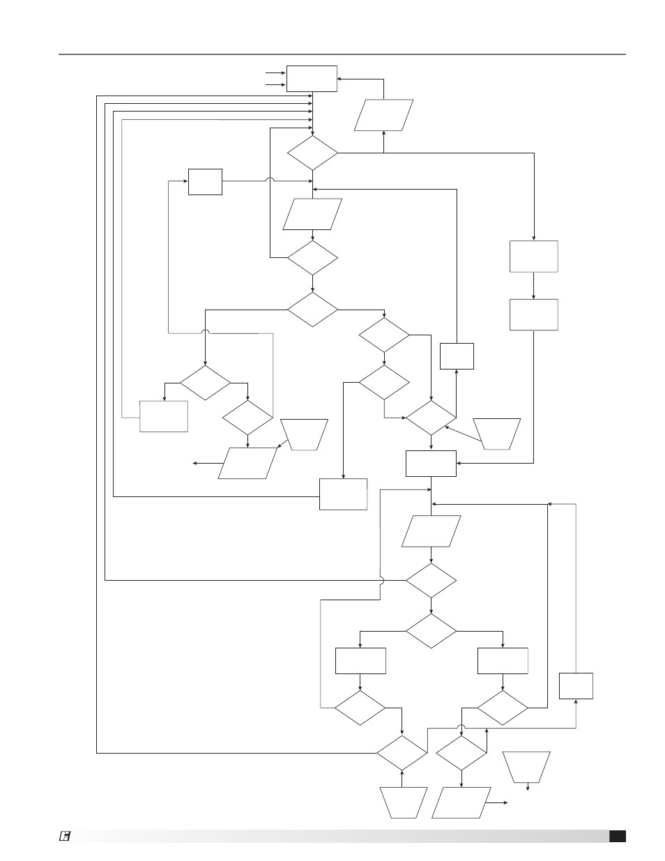
General Electrical Controls Information
VGN Technology Control Flow Chart - Single Fan
Positive Pressure Fault
Negative Pressure Fault
Above Setpoint
(more positive)
Send to BMS
Controller
Send to BMS
Controller
Below Setpoint
(more negative)
Above Setpoint
(more positive)
Below Setpoint
(more negative)
Yes
Yes
No
No
No
No
No
No
No
No
No
No
No
Yes
Yes
Yes
Yes
No
Yes
Yes
Yes
Yes
Yes
Yes
Yes
Yes
BMS Control
Drive Fault
Alarm
Drive
Fault Bypass
Mode
Static
Pressure =
Setpoint
Fan at
Full Speed
Required
Nozzle Area
Static
Pressure
Value
Static
Pressure
Valve
VFD
at Full
Speed
Increase
Fan Speed
Positive
Pressure
Alarm
Negative
Pressure
Alarm
Time Period
Met?
Max. VFD
Monitor
Time
Min. VFD
Monitor
Time
Damper
Position
Monitor
Time
Time Period
Met?
Time Period
Met?
Time Period
Met?
BMS Control
Bypass Damper
PID
Decrease
Fan Speed
Static
Pressure
Value
Open
Bypass
Damper
Close
Bypass
Damper
Bypass
Feedback
= Maximum
VDC
Bypass
Feedback
= Mimimum
VDC
Reset by
BMS
Reset by
BMS
Reset at
Fault CLR
Reset at
Fault CLR
Nozzle
Feedback at
Minimum
VFD at
Minimum
Speed
Static
Pressure =
Setpoint
Static
Pressure
Value
5
VGN Technology
®