Left side connections -3, Electrical connections -3, Left side connections – Hypertherm LR2075 User Manual
Page 18: Electrical connections
INSTALLATION
LR
2075 Laser Head Instruction Manual
3-3
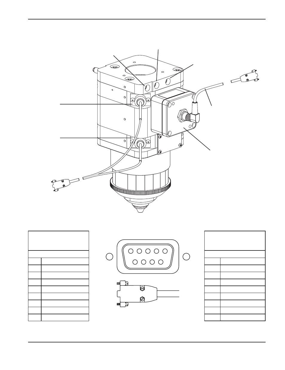
Left side connections
Purge gas:
1/8" NPT, internal thread
Cutting gas:
1/8" NPT, internal thread
Cooling water (in/out):
1/8" NPT, internal thread
Lens interlock
switch and cable
(7.5" lens bay)
Lens interlock
switch and cable
(5" lens bay)
Capacitive height sensor:
amplifier assembly
Capacitive height sensor:
cable
Electrical connections
Capacitive height sensor
Sockets (female)
cable signal list
Socket #
Description
1
+ 15 VDC
2
Common
3
– 15 VDC
4
Analog output
5
Analog common
6
Tip touch TTL output
7
N/C
8
N/C
9
Shield
Lens interlock switches
Pins (male)
cable signal list
Pin #
Description
1
*Collision mount 1 +
2
*Collision mount 2 +
3
N/C
4
7.5" lens interlock +
5
5.0" lens interlock +
6
*Collision mount 1 –
7
*Collision mount 2 –
8
7.5" lens interlock –
9
5.0" lens interlock –
1
2
3
4
5
6
7
8
9
9 pin connector
* The collision mount is an optional feature