Controller cable connector information -8, Connect cables -8 – Hypertherm LH2100 User Manual
Page 23
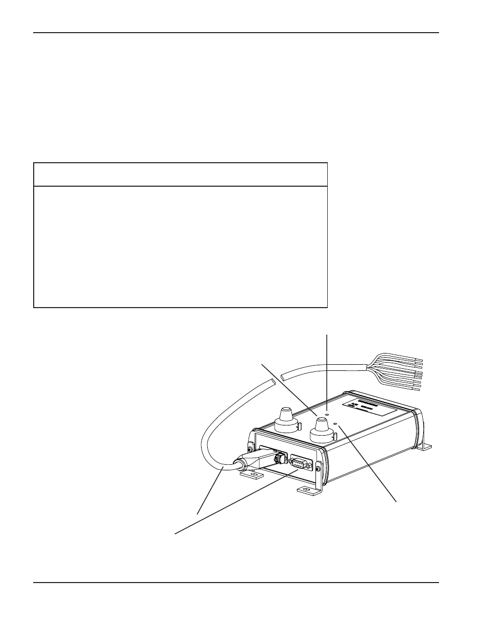
Connect cables
Interface box (CHS) 15-pin cable to controller
Amplifier module to interface box (CHS)
1
INSTALLATION
3-8
LH2125/LH2100 Laser Head Instruction Manual
Capacitive height sensor (CHS) interface box installation
The amplifier module will be mounted to the laser head if the capacitive height sensing option was ordered. Choose a
suitable location for the CHS interface box.
Controller cable connector information (15 pin D-Sub)
Pin-outs (Output To Controller)
Note: Outputs are dry-contact relay outputs.
Pin
Wire
Number
Color
Description
1
Blue
Not used
2
Purple
Not used
3
Brown
Over-range +
4
Grey
Over-range -
5
Yellow
Tip-touch +
6
Green
Tip-touch -
7
White
Distance signal +
8
Orange
Distance signal -
9
Red
+ Volt input (9-36 VDC)
10
Black
- Volt input
11-14
Not used
15
Shield
Electromagnetic Protection (earth ground)
Power indicator
Over-range indicator
Under-range indicator
(not shown)