Single channel interface adjustments -5, Cut-error monitor -5, Precision adjustments -5 – Hypertherm LH2100 User Manual
Page 32: Cut-error monitor -5 precision adjustments -5, Single-channel interface adjustments
1
OPERATION
LH2125/LH2100 Laser Head Instruction Manual
4-5
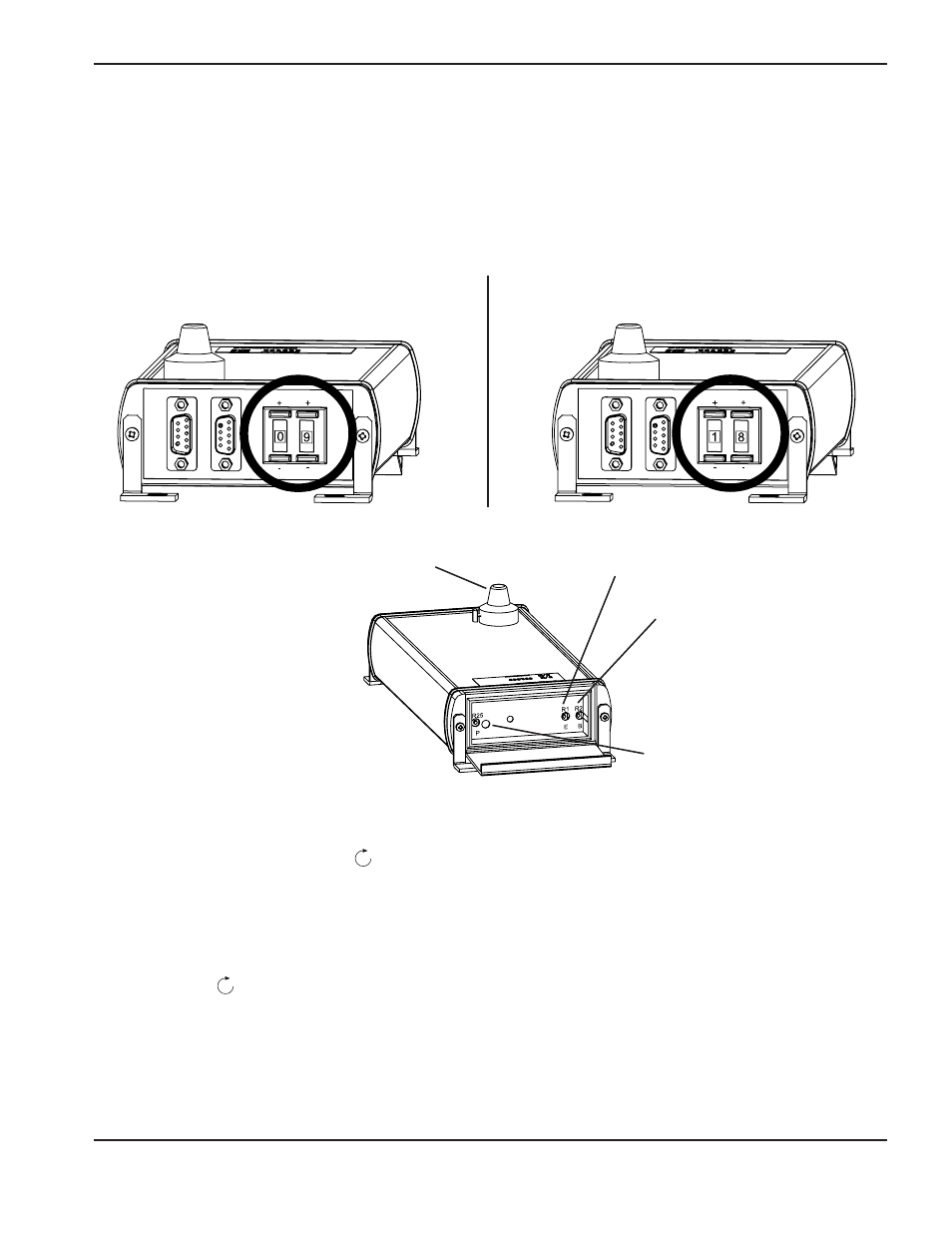
Single-channel interface adjustments
Cut-error monitor:
(continuously monitors the cutting process.)
The cut-error monitor is intended for steady-state cutting. An error condition may be recorded in transient operations,
such as near a sharp corner, and should be ignored. Set the error-compensation adjustment for the specific cutting
conditions.
Material Thickness, 6 mm (1/4") or more, Setting = 18
Material Thickness, 6 mm (1/4") or less, Setting = 09
General error-compensation settings
Precision adjustments
The cut error monitor sensitivity can be changed with potentiometer R1 (E). If false error signals
1
are seen consistently
during good cutting, turn R1 clockwise
to increase the sensitivity limit.
Test and fine-tune the sensitivity levels of each output for error parameters. The cut error monitor is intended for steady
state cutting operations. Any error reported during transient operations, such as near a sharp corner, should be ignored.
Blast pierce/continuous wave (strong):
(laser on, with the cutting gas at maximum power)
Blast pierce sensitivity can be changed with potentiometer R2 (B). If the circuit is giving a late pierce complete signal
2
,
turn R2 clockwise
to increase the sensitivity limit
3
. If the blast piercing method is utilized, the pulse pierce output
should be ignored.
Note
1
: A false error signal represents an error reported during acceptable cutting..
Note
2
: Output is not switching within 1/2 second of when pierce is complete. This can be observed
visualy
Note
3
: Use 1/2 turn increments when adjusting sensitivity
R2 (B)
R1 (E)
Gain adjustment knob
Pierce pulse LED indicator