Powermax1650, Maintenance, Service manual – Hypertherm Powermax1650 Service Manual User Manual
Page 37
MAINTENANCE
3-10
powermax1650
Service Manual
0
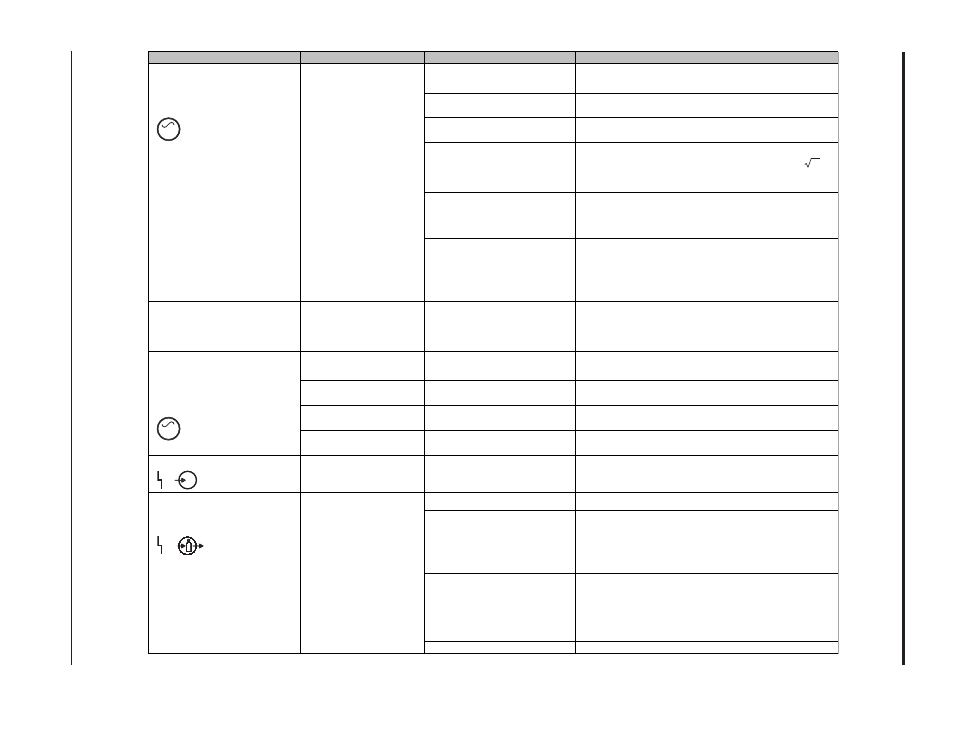
Problem
This May Mean
Cause
Solution
No voltage or improper voltage
applied to unit
Verify incoming voltage is between 200-600 VAC.
Defective power switch (S1)
Measure AC voltage at bottom terminals of switch. If no
voltage, replace switch.
Defective filter board (PCB1)
CE System only: Measure AC voltage at input diode
bridge. If no voltage or low voltage, replace filter board.
Defective input diode bridge
(D24)
Measure DC voltage on input diode bridge. Voltage at
input diode bridge should be approximately Vin * 2. If
incorrect voltage or no voltage, replace input diode
bridge.
Defective power board (PCB2)
or IGBT module (Q14)
Bus voltage should be 750 VDC when input voltage is
between 200-540 VAC. If voltage is incorrect, inspect
power board and IGBT module for damage.
Defective power board (PCB2)
or control board (PCB3)
Disconnect power board J4 connector and measure for
VDC on power board TP1: J4-Pin16 = 5 VDC, J4-Pin18
= 5 VDC with start switch depressed. If incorrect
voltage or no voltage, replace power board. If voltage is
correct, replace control board.
Red LED on power board
(PCB2) illuminates when
input voltage is between 200-
540 VAC
Defective boost IGBT module
(Q14) or power board (PCB2)
Replace boost IGBT (Q14) and inspect power board
(PCB2) for damage.
System is in gas test
mode
Current adjustment knob is in
gas test position
Turn knob clockwise until above the 25 amp setting.
Solenoid valve (V1) stuck
open
Faulty valve
Disconnect J20 from power board (PCB2). If air flow
continues, replace valve (V1).
Defective power board
(PCB2)
Constant voltage supplied to
valve
Disconnect J20 from power board (PCB2). If air flow
stops, replace power board.
Incoming gas pressure is
too high
Incoming gas pressure is
above 120 psi (8.3 bar)
Set incoming gas pressure between 90 psi (6.1 bar)
and 120 psi (8.3 bar).
Voltage LED illuminates
Improper line voltage
Voltage below proper operating
limits or loss of phase
Verify incoming line voltage.
No air supplied to unit
Connect air supply.
Air pressure below operating
requirement
Turn current adjustment knob to gas test and set
pressure to 75 psi (5.2 bar) for cutting and 50 (3.4 bar)
for gouging is required for system operation. Check
that the inlet gas pressure is within setup specifications
in section 2.
Faulty pressure sensor
assembly
With normal air supply (>90 psi) connected, measure
R47 left to TP1 with a DC digital voltage meter. Voltage
should be approximately 3.3V when regulator is set at
70 psi. Change regulator setting and verify that voltage
also changes.
Dirty air filter element
Replace air filter element.
Turn power switch ON and
Power On LED does not
illuminate
Insufficient voltage to
control circuits or shorted
power component
Air pressure LED blinks
yellow
Insufficient air pressure
Power LED illuminates and
air flows from torch (torch
trigger/start switch not
pressed)
AC
AC
V