Powermax1650, Maintenance, Service manual – Hypertherm Powermax1650 Service Manual User Manual
Page 40
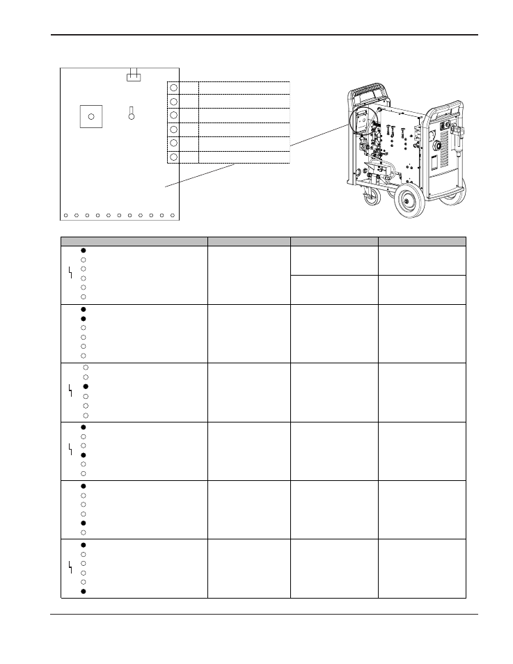
This May Mean
Cause
Solution
Start LED on control board
(PCB3) and Fault lamp are
illuminated
Continuous start signal
Shorted start wires or
depressed start trigger
switch
Check start wires (blue
and orange wires in torch)
for short.
Receiving start signal from
CNC
Check CNC cable for start
signal (Machine interface
pins 3 and 4).
Start and XFR LEDs on
control board (PCB3)
Arc transfer
Normal operation
N/A
SDF LED on control board
(PCB3) and Fault lamp are
illuminated
Self diagnostic failure
Microprocessor failure
Replace control board
(PCB3). If SDF LED
persists replace power
board (PCB2).
Start and IF LEDs on
control board (PCB3) and
Fault lamp are illuminated
Invertor interlock
No current from invertor,
power board (PCB2),
control board (PCB3), or
IGBTs
Start and TSO LEDs on
control board (PCB3)
Torch stuck in open
position
Torch plunger stuck,
consumables are worn, or
defective Pilot Arc IGBT
See Resistance Check
#3, in this section.
Start and SP LEDs on control
board (PCB3) and Fault lamp
are illuminated
LED is for future use
N/A
N/A
Problem
MAINTENANCE
powermax1650
Service Manual
3-13
0
(VISIBLE FOR 10 SEC. AFTER EVENT)
TORCH STUCK OPEN
(VISIBLE FOR 10 SEC. AFTER EVENT)
70
50
STATUS
GAS
45
60
55
65
75
80
85
TSO
SP
SPARE
DIAGNOSTIC LED'S
START SIGNAL VALID
INVERTER INTERLOCK
(BLINKING @ 1 SEC. RATE)
SELF DIAGNOSTICS FAILURE
CPA
NORMAL
GOUGE
CURRENT
DOWN
MID
UP
P1
XFR
SDF
IF
TRANSFER
START
START
XFR
START
SDF
IF
START
TSO
START
SP
START