Infloor TC 204 Heating Controller User Manual
Page 2
This comes in the package:
TC204 Controller mounted on a standard
4” x 4” electrical box
1 Outdoor Sensor
1 Supply Water Sensor
2 Cable Connectors (inside the electrical box)
1 Instruction Manual
Provided by installer:
120/24 Vac Transformer, 25 - 40 VA
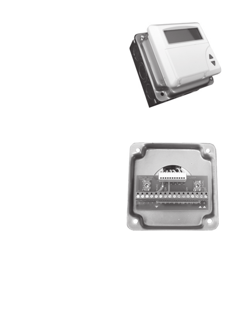
The TC204 is connected to an external terminal
board secured to the under-side of the 4” x 4”
cover. This simplifies field wiring as there is no
need to open the controller itself.
The controller is pre-programmed with defaults
that match most heating systems in the northern
States & Canada. Typically no other adjustments
are needed but are easy to do, following instruc-
tions in the operations manual.
Let the system stabilize before making
changes to control parameters.
Notes:
The TC 204 can be removed from the steel box cover and the external terminal board for
installation directly in an occupied space.
Loosen the connector on the circuit board and then the center screw under the lid of the controller.
Pry off the front of the controller and remove the two screws holding the terminal board.
For wiring of other applications, such as direct control of boilers in sequence, see the manuals on
our website www.paxtoncorp.com.
Installation:
Remove the two screws in the corners of the 4” x 4” box
and lift off the cover. The controller is secured to this cover.
Set aside the 2 cable connectors located inside the box.
Install the box on a wall near the mixing valve or boiler,within
reach of the actuator cable. Or inside the mixing station
enclosure if there is space available.
Remove 1 or 2 knockouts and insert the cable connector(s).
Run the power supply, sensor, and output wires into the box.
2