Infloor TC 204 Heating Controller User Manual
Page 4
Advertising
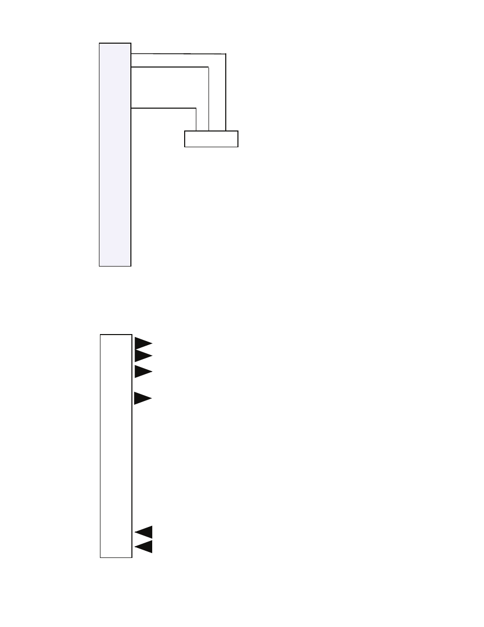
Note:
The 2 terminals marked L1 are not the
same.
The left one drives the actuator clock-
wise and the right one drives the actuator
counter-clockwise.
Output 2 on the TC204 increases heat.
VM92 Actuators
1. Output to actuator – Less Heat
2. Output to actuator – More Heat
3. Pump start/stop (use external relay)
4. input for remote operation
5. Output to actuator 24 Vac
6. Common
6. Common
7. Return water or room sensor (optional)
8. Supply water sensor (must be used)
9. Outdoor sensor
10. Auxiliary output 10 Vdc
6. Common
11. ModBus A+ communication
12. ModBus B- communication
5. 24 Vac Power supply (hot side)
6. 24 Vac Power supply (common)
Always use this pair of ter-
minals for the power input.
�
�
�
�
�
�
�
�
�
�
��
�
��
��
�
�
����������
�
�
�
�
�
�
�
�
�
�
��
�
��
��
�
�
4
Advertising