Main switch i/o, Operation of cooling unit (procool 10/30) – Kemppi Promig 100 User Manual
Page 13
Promig 100/0450 – 13
©
COPYRIGHT
KEMPPI
OY
E
B
D
C
A
F
G
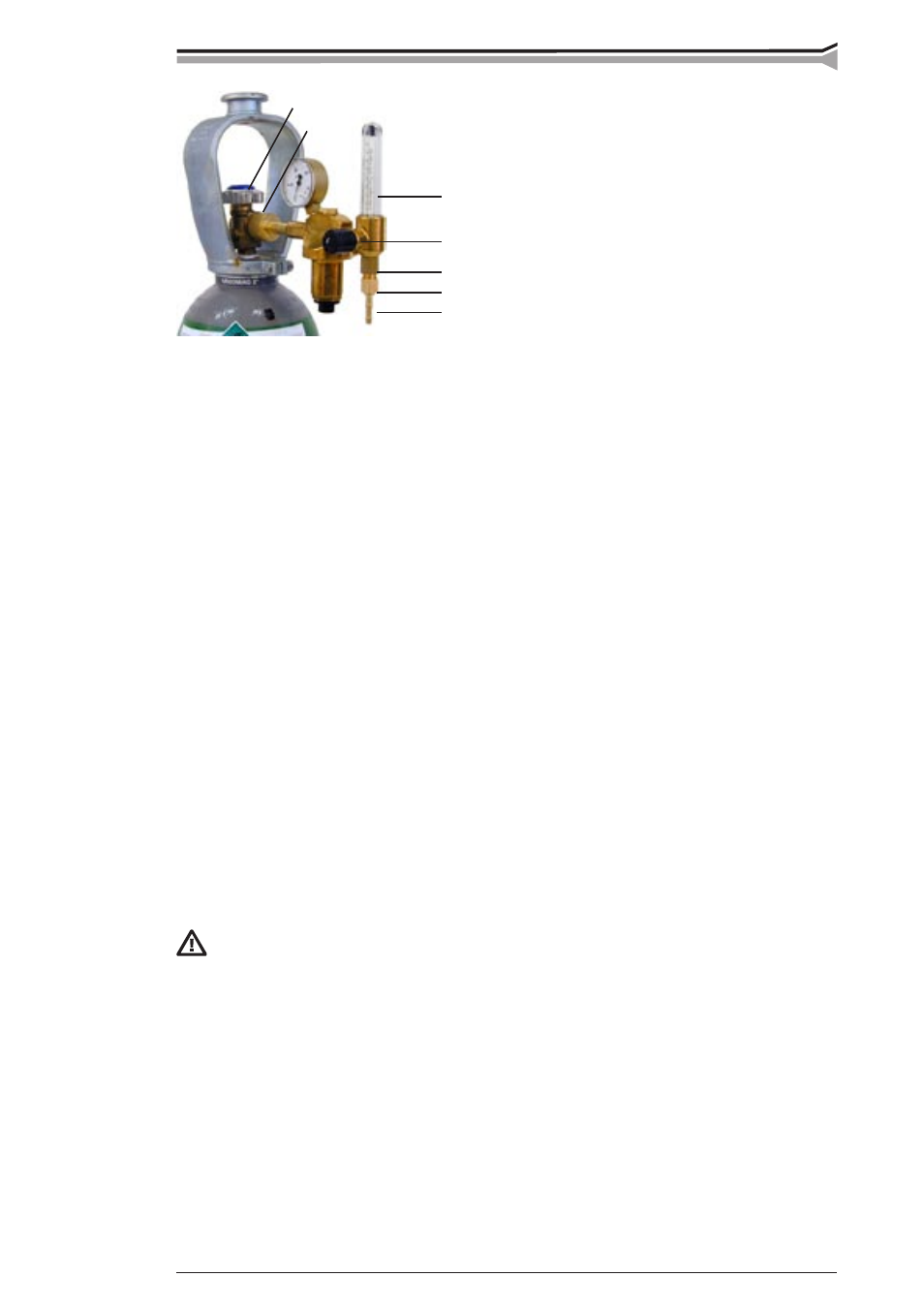
Parts of gas flow regulator
A Gas bottle valve
B Press regulation screw
C Connecting nut
D Hose spindle
E Jacket nut
F Gas bottle pressure meter
G Gas hose pressure meter
The following installing instructions are valid for most of the gas flow regulator types:
1. Step aside and open the bottle valve (A) for a while to blow out possible impurities from
the bottle valve.
2. Turn the press regulation screw (B) of the regulator until no spring pressure can be felt.
3. Close needle valve, if there is one in the regulator.
4. Install the regulator on bottle valve and tighten connecting nut (C) with a wrench.
5. Install hose spindle (D) and jacket nut (E) into gas hose and tighten with hose clamp.
6. Connect the hose with the regulator and the other end with the wire feed unit.
Tighten the jacket nut.
7. Open bottle valve slowly. Gas bottle pressure meter (F) shows the bottle pressure.
Note! Do not use the whole contents of the bottle. The bottle should be filled when the
bottle pressure is 2 bar.
8. Open needle valve if there is one in the regulator.
9. Turn regulation screw (B) until hose pressure meter (G) shows the required flow
(or pressure). When regulating flow amount, the power source should be switched on and
the gun switch pressed simultaniously.
Close bottle valve after having finished welding. If the machine will be out of use for a long
time, unscrew the pressure regulation screw.
2.4. MAIN SWITCH I/O
When you turn the main switch of the Pro power source into I -position, pilot lamp close to it
is lighted and the equipment is ready for welding. The equipment is returned to that welding
method with which the welding was last carried out before the main switch was turned to
zero position.
Always start and switch off the machine with the main switch, never use the
mains plug as a switch.
2.5. OPERATION OF COOLING UNIT (PROCOOL 10/30)
Operation of cooling unit is controlled in such a way that pump is started when welding is
started. After welding stop pump is rotating for approx. 5 min cooling the liquid to ambient
temperature. Purpose of this operation is to make maintenance intervals of pump longer.
Read in operation instructions for the Procool 10/30 unit the trouble situations of the liquid
circulation system and protection against torch etc. damage.