K-Patents PR-33-S User Manual
Page 11
2 Ethernet connection
7
© Copyright K-Patents 2015. All rights reserved.
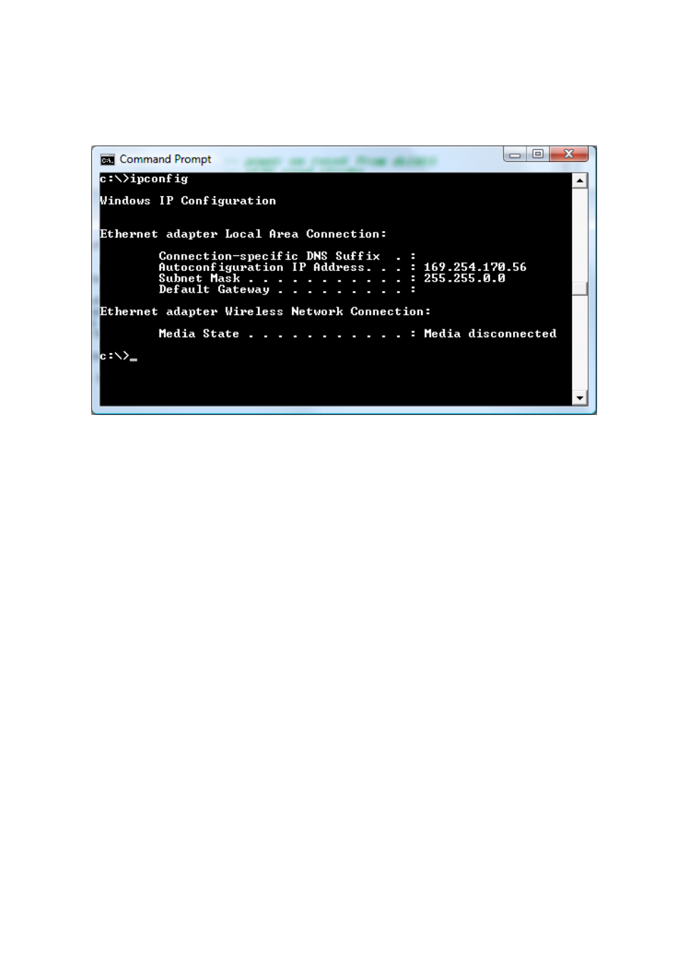
Figure 2.5
Typical IP configuration for a stand-alone laptop when
connected to a sensor; laptop wireless (WLAN) is turned off
Note: The connection will not work if the computer and the sensor have exactly the
same IP address.
When you have configured the network settings of the sensor (and/or the computer)
according to the instructions above, you can proceed to test the connection as in-
structed below in Section 2.3.
2.2.3 Configuring a network of sensors
In case you have more than one sensor in a network, the sensor IP addresses have to
be configured, as the factory default will not work.
If you are connecting the sensor to a factory network, please consult the network ad-
ministrator for the correct settings.
If the network is a stand-alone network with only PR-33’s and one or more computers
with no connection to any other network, then the IP addresses can be chosen rather
freely. One possibility is to number the instruments so that they all have 192.168.33.x
addresses so that every computer and instrument has a different number x between
1...254. The subnet mask (or netmask) is in this case 255.255.255.0 (see figure 2.6).