Fence assembly parts diagram, Assembly - fence – Kreg Precision Miter Gauge System User Manual
Page 6
Advertising
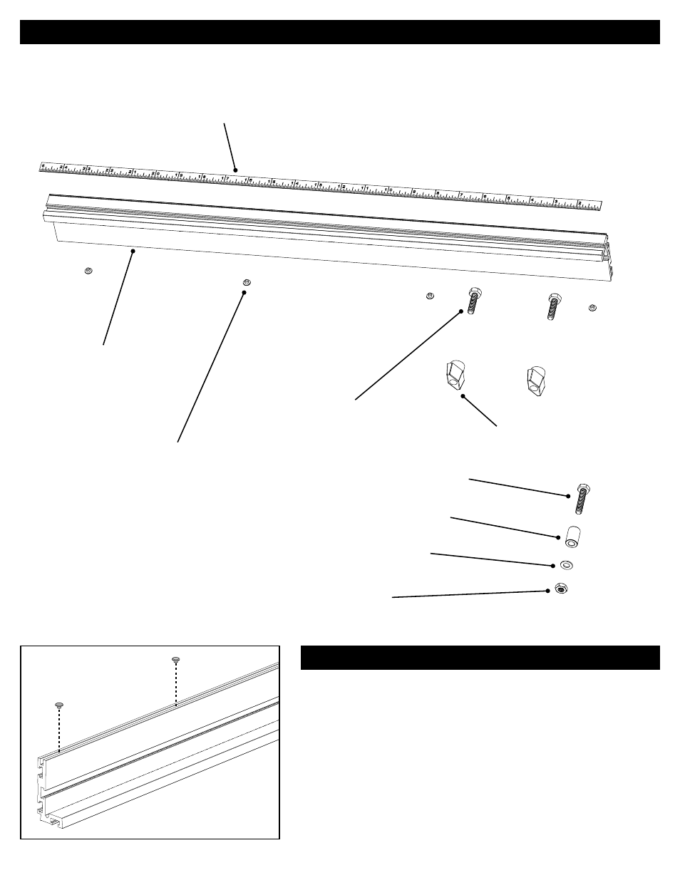
Assembly - Fence
6.
Press the four plastic glides into the groove in the bottom of the fence,
placing one about 1" from each end and the other two spaced evenly
between them.
Install the fence glides
Fence Assembly
Parts Diagram
(1) 48" right-to-left reading self-adhesive tape
FT4047
(6) Glides
FT4055
(1) Fence extrusion
KMS7702
(2) ¼"-20 x 1" hex head bolts
FT4139
(2) T-knobs
DK1313
(1) ¼"-20 x 1¼" hex head bolt
FT4059
(1) ¼" brass washer
DK1504
(1) ¼"-20 hex nut
DK1510
(1) Fence Stop
FT4203
Advertising