Waveport/v devices, Overview – Measurement Computing WavePort rev.3.0 User Manual
Page 35
WavePort User’s Manual
09-29-00
Hardware and Operation Reference 4-7
WavePort/V Devices
Overview
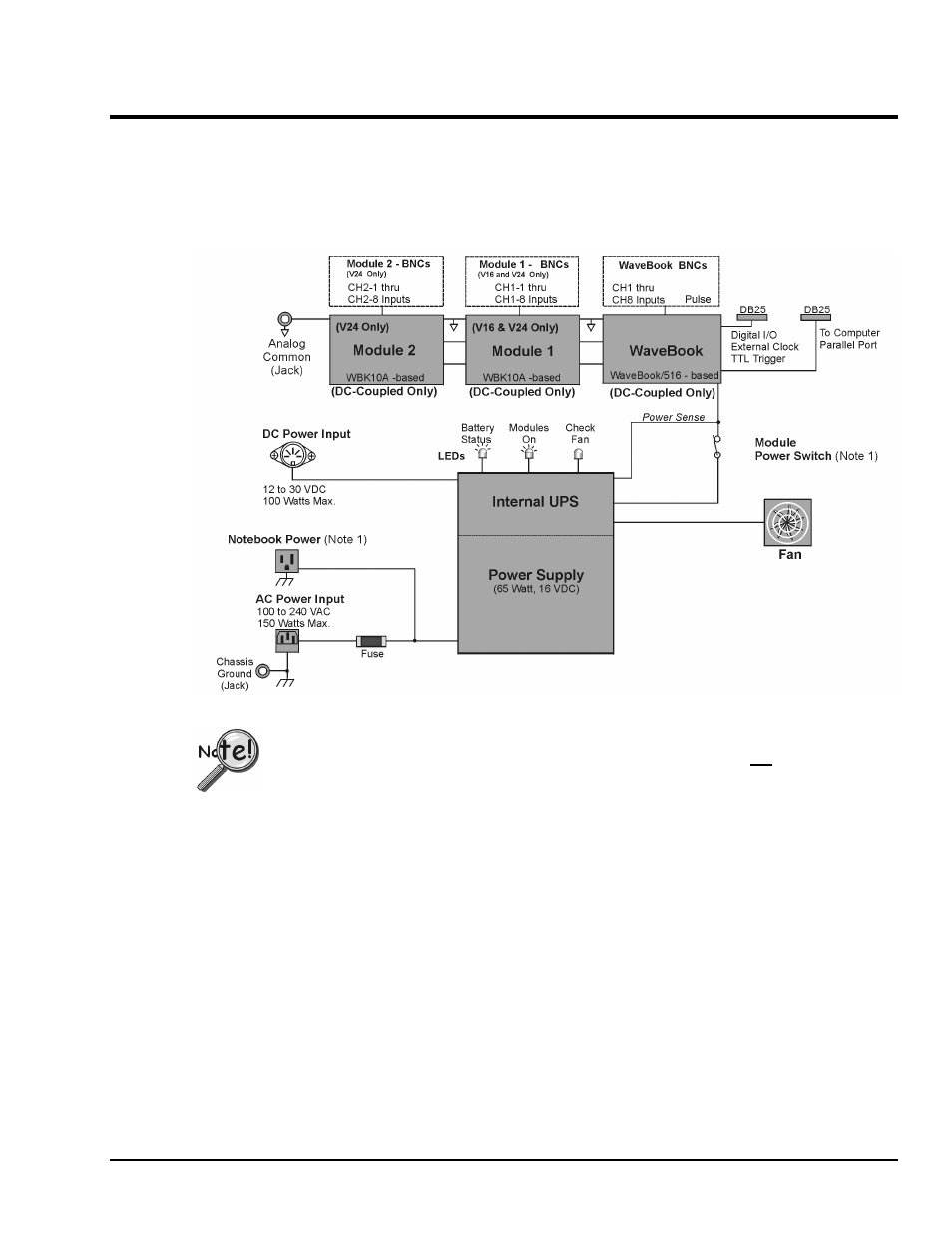
The following block diagram serves to provide a general understanding of WavePort/V devices. Detailed
information regarding such items as the signal and power modules, indicator lights, and the unit fan are
included later in this chapter.
WavePort/V, Simple Block Diagram
The Notebook Power receptacle on WavePort’s cover plate is “LIVE” whenever WavePort is
connected to a “live” AC power source. The Module Power Switch can not be used to turn
off the Notebook Power Receptacle.
From the diagram we can see that WavePort/V24 consists of:
• Two Analog Input Modules (Module 2 and Module 1).* Both modules provide for 8 input channels
(through BNC connectors). These modules are based on WBK10A architecture.
• One WaveBook Module. This module provides for 8 analog channel inputs through BNC connectors
and a Pulse input.
• A 65 watt, 16 VDC Power Supply and Internal UPS (Uninterruptible Power Supply) System
• Two 25-pin connectors (DB25). One for connecting to the Notebook’s parallel port and another for
connecting to Digital I/O, External Clock, and TTL Trigger signals
• Three electrical connectors: DC Power Input, AC Power Input, and AC Auxiliary Output
• Three Indicator Lights: for “Battery” Status, indication of “Modules On,” and “Fan” On
• Fan, variable speed to provide system cooling
*In the WavePort/V product line, only WavePort/V24 includes a WaveBook module plus two additional
analog input modules (Module 1 and Module 2). WavePort/V8 includes the WaveBook module, but has
no WBK10-based modules. WavePort/V16 includes the WavePort module and the WBK10A-based
Module 1.