Digital-pattern trigger, Multi-channel triggering – Measurement Computing WavePort rev.3.0 User Manual
Page 42
4-14 Hardware and Operation Reference
09-29-00
WavePort User’s Manual
Digital-Pattern Trigger
This type of trigger is useful when trying to capture noise, vibrations or some other physical disturbance
that occurs at a particular point in a digitally-sequenced process, such as a relay-logic-control system.
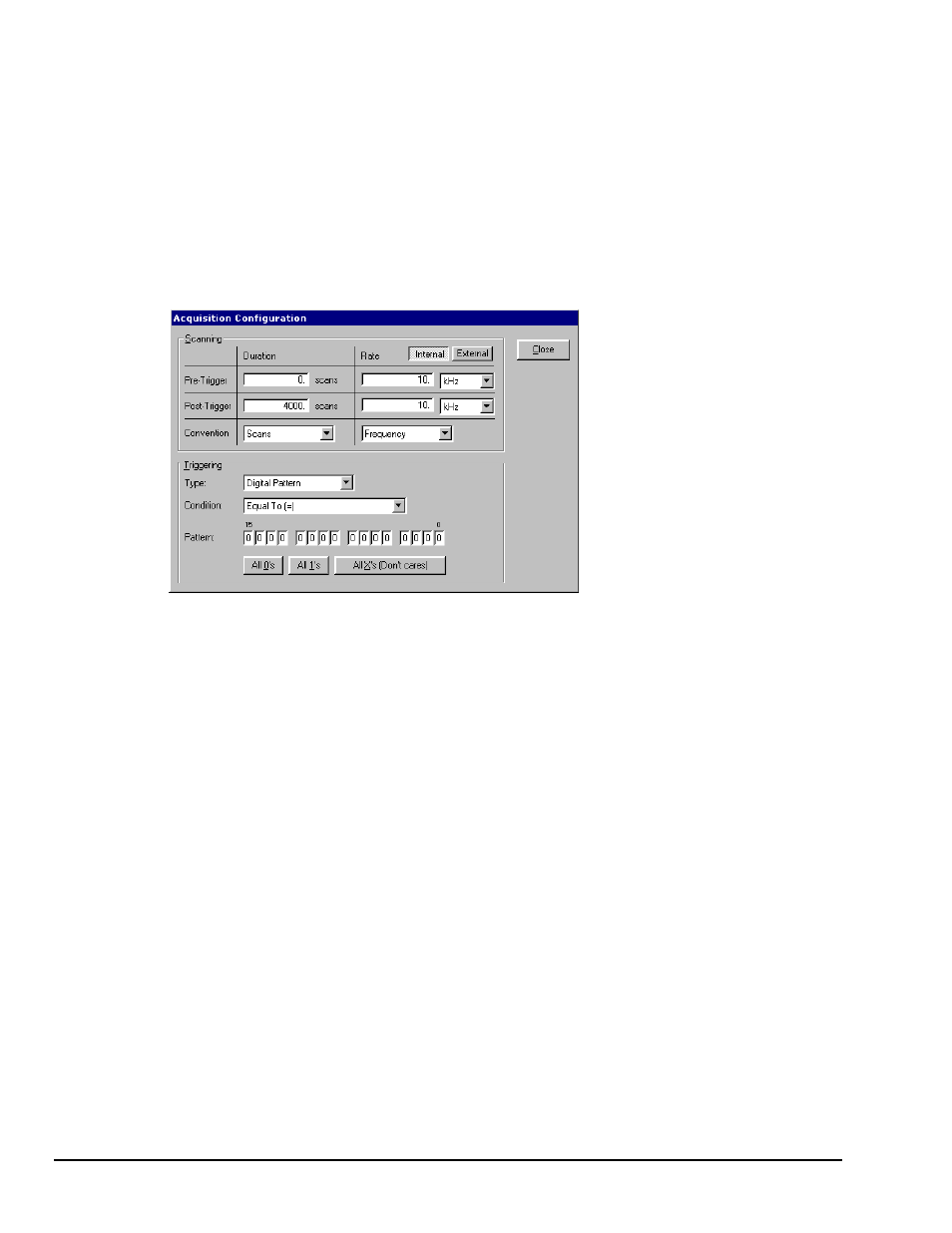
When “Digital Pattern” is selected as the Triggering Type, the 16-bit pattern extension appears (as indicated
in the following figure). The Condition box allows the following choices:
Equal To (=) / Not Equal To (< >) – These options treat each digital line as a separate input to be
compared to logical 1 or 0. Selecting “Equal To” triggers only on the exact pattern of 1’s and 0’s selected.,
while “Not Equal” triggers on all others. You can also set any of the inputs to “don’t care” (X), which
excludes it from the comparison.
Greater Than (>) / Less Than (<) – These options interpret the digital inputs as a single 16-bit value and
allow a threshold trigger.
Acquisition Configuration Dialog Box, with Digital Pattern Extensions
Note:
The top row contains a button labeled “External” for enabling the External Clock.
Multi-channel Triggering
Multi-channel triggering allows you to select a combination of analog input channels as the analog
trigger, including any of its 64 optional expression channels. You can set trigger-level slope, polarity, and
hysteresis for each trigger channel, then combine the trigger channels in a logical “and/or” function to
define the desired trigger condition. This is made possible by Signal Digital Processing (DSP). DSP
initiates sampling of the trigger channels, calibrates the incoming data, compares readings to
pre-programmed trigger states, and then determines whether or not trigger conditions are satisfied.