Imer …… 6-15, External clock and counter-timer – Measurement Computing WavePort rev.3.0 User Manual
Page 67
WavePort User’s Manual
09-29-00
WaveView 6-15
◊ Above Thresh. A trigger channel is valid whenever the signal level is above the trigger level and stays
valid until the signal level goes below the trigger level by at least the user-set hysteresis amount.
◊ Below Thresh. A trigger channel is valid whenever the signal level is below the trigger level and stays
valid until the signal level goes above the trigger level by at least the user-set hysteresis amount.
◊ Latch Rising Edge. The signal level must first go below the trigger level by the user-set hysteresis
amount. Then, the trigger channel is valid whenever the signal level is above the trigger level and stays
valid until the acquisition is complete.
◊ Latch Falling Edge. The signal level must first go below the trigger level by the user-set hysteresis
amount. Then, the trigger channel is valid whenever the signal level is below the trigger level and stays
valid until the acquisition is complete.
◊ Latch Above Thresh. A trigger channel is valid whenever the signal level is above the trigger level and
stays valid until the acquisition is complete.
◊ Latch Below Thresh. A trigger channel is valid whenever the signal level is below the trigger level and
stays valid until the acquisition is complete.
Note: The threshold voltage and hysteresis level may be set for each channel as required. Position the
cursor per channel and enter the desired value(s).
External Clock and Counter-Timer
WavePorts can receive an external clock input through pin 20 of the DB25 connector labeled DIGITAL
I/O, EXTERNAL CLOCK, TTL TRIGGER. This enables data scanning to be correlated with an external
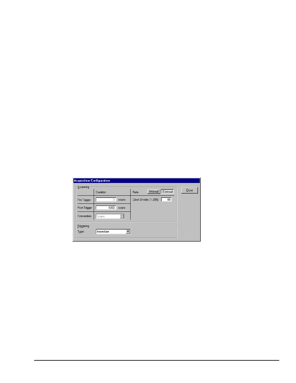
pulse train. To enable the external clock, select “External” for the Scanning Rate in the Acquisition
Configuration Dialog Box (see following screen shot). When the external clock is enabled, WavePort
begins a scan only after a rising edge on the TTL level occurs. Optionally, the external clock may be
divided [by a factor of 1 to 255]. This “pre-scaling” allows the user to select a reduced scan rate.
Acquisition Configuration Dialog Box with External Clock Enabled
Note: Clock Divider can be set from 1 to 255
WavePort has a 32-bit internal counter that calculates and reports the external clock’s period. The counter
can be read with each scan of the analog data. This is often beneficial in later analysis, when there is a need
to correlate physical phenomena with speed.
The counter channel actually consists of two independent channels (CtrLo and CtrHi). These can be turned
“On” in the Channel Configuration Spreadsheet. When enabled, the low (CtrLo), then high (CtrHi) words
of the counter will be configured in each scan. Note that the spreadsheet’s Units column can be used to
view a predefined period in units of seconds, ms, or µsec.
WaveView can be configured to read only the low word of the counter data (CtrLo:“On,” CtrHi: “Off”).
This decreases the minimum scan period by 1 usec. This LoCtr only option can be used only when the
external clock frequency is greater than 305 Hz (20,000,000 MHz / 65536]. Note that WaveView does not
enforce this.