Chapter 6 - waveview, Waveview 6 – Measurement Computing WavePort rev.3.0 User Manual
Page 53
WavePort User’s Manual
09-29-00
WaveView 6-1
WaveView
6
Software Setup Notice for WavePort… 6-1
Introduction…… 6-2
Software Startup & Sample Acquisition…… 6-2
Startup WaveView…… 6-2
Configure Channels…… 6-4
Configure Acquisition…… 6-5
Collect Data…… 6-6
Store Data [and View File Data], Option…… 6-7
WaveView Configuration Main Window…… 6-7
Menu Items & Buttons…… 6-7
File…… 6-8
Edit…… 6-8
View…… 6-8
System…… 6-9
Input Channel Configuration…… 6-10
Data Conversion…… 6-12
Acquisition Configuration…… 6-13
General Information ….. 6-13
Trigger Types ….. 6-14
External Clock and Counter-Timer …… 6-15
Digital Pattern Trigger…… 6-16
Pulse Trigger …… 6-17
WaveView Scope Window…… 6-18
Menu Items & Buttons…… 6-19
File…… 6-19
Acquire…… 6-19
Charts…… 6-19
Scope Display…… 6-20
WaveView Direct-To-Disk Window… 6-21
Software Setup Notice for WavePort
WavePort/PE16 makes use of two Dynamic Signal MODULES (WBK14); WavePort/PE8 makes use of
one such module. You must set pertinent software parameters from the WaveView Configuration main
window. Related Input Channel Configuration information begins on page 6-10.
In WaveView, WavePort/V8 appears as a WaveBook. The other two WavePort/V versions (V16 and
V24) appear as a WaveBook and one (or two) WBK10A modules. WavePort/V24 makes use of two
Analog Expansion MODULES (WBK10A); WavePort/V16 makes use of one such module. You must set
pertinent software parameters from the WaveView Configuration main window. Related Input Channel
Configuration information begins on page 6-10.
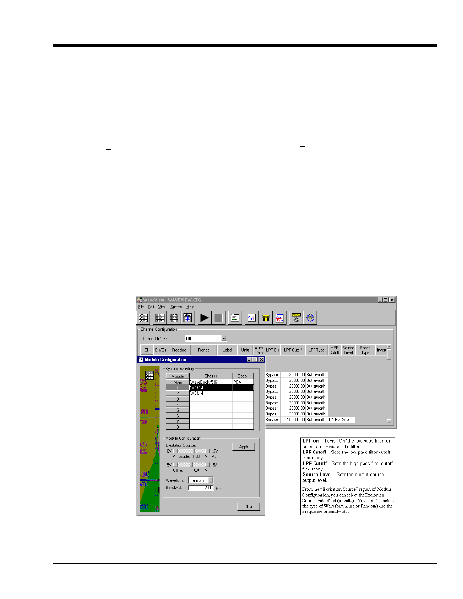
The Module Configuration window allows you to set the following Excitation Source parameters:
amplitude, offset, waveform, and frequency.
WaveView and Module Configuration Windows
WavePort/PE units appear as a WaveBook with one WBK14 (PE8), or two WBK14s (PE16).
WavePort/V units will appear as a WaveBook with one WBK10A (V16), two WBK10As (V24), or none (V8).
Note
: WBK14-related information does not apply to WavePort/V units.