Microcom 470 User Manual
Page 22
Communications
Chapter 3
))))))))))))))))))))))))))))))))))))))))))))
))))))))))))))))))))))))))))))))))))))))))))
470 Operators Manual
14
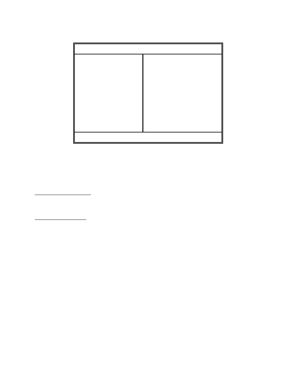
Parallel Port Configuration
1 = /STROBE
2 = D0
3 = D1
4 = D2
5 = D3
6 = D4
7 = D5
8 = D6
9 = D7
10 = /ACK
11 = BUSY
12 = PAPER OUT
13 = SCLT
14 = NC
15 = NC
16 = LOGIC GND
17-18 = NC
19-30 = LOGIC GND
31 = /INIT
32 = /ERROR
33 = LOGIC GND
34-36 = NC
(36 PIN CENTRONICS®)
Table 2
3.2
PRINTER CABLES
For parallel connection:
Use a standard 36 pin male Centronics® to 25 pin male cable,
connected from the desired parallel port of the host computer to
the 36 pin connector on the 470.
For serial connection:
If your host computer has a...
9 pin serial com port -
Use a 9 pin female to 9 pin male video extension cable. (pin #1 to
pin #1...)
25 pin serial com port -
Use a standard 25 pin male to 9 pin male serial cable.
Note: NULL modem cable adapters are not necessary since the printer is DCE equipment.